


American Hydraulic Retarder Now Available in Britain
Page 44
If you've noticed an error in this article please click here to report it so we can fix it.
OBSERVED by a member of the staff of The Commercial Motor, a fully laden maximum-load fourwheeler descended Sunrising Hill, Warwick, in neutral at a substantially constant speed of about 20 m.p.h., and later descended Edge Hill at a steady speed of around 30 m.p.h., without the use of the friction brakes on either run.
The steepest gradient of Sunrising Hill is I in 61, whilst Edge Hill has a maximum gradient of approximately I in 8, the average in both cases being steeper than 1 in The test vehicle was a Foden operated by the research department of the Lockheed Hydraulic Brake Co., Ltd., Leamington Spa. and it was equipped with the Thompson hydraulic retarder, which will be shown on the stand of the Automotive Products Co., Ltd., at Earls Court.
The retarder provides a rate of negative acceleration of 15 per cent., which is equivalent to holding a vehicle stationary on a gradient of 1 in 61. Efficiency of the system tends to increase with road speed, but is not seriously affected by a reduction in m.p.h. until the vehicle speed drops to a walking pace.
Proved in U.S.A.
Fully tested in America, the equipment has been applied in that country to a variety of goods and passenger vehicles.
Application of the retarding farce is smooth and progressive and does not impose shock loads on the transmission. Moreover, the retarder can be usefully employed as an adjunct to normal braking on less severe inclines and on flat road surfaces, as well as the main braking system on long descents. It is particularly useful in controlling the vehicle on icy roads. Normal application lag is about 2 seconds.
In addition to the hydraulic retarder unit, essential components include an airoperated loading cylinder and a heat CS exchanger. This is incorporated in the cooling system of the power unit and is employed to reduce the temperature of the fluid heated by the retarder when it is acting as a brake.
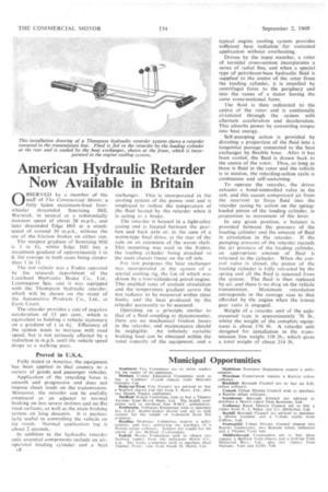
The retarder is housed in a light-alloy casing and is located• between the gearbox and back axle or, in the case of a worm-type final drive, at the rear of the axle on an extension of the worm shaft. This mounting was used in the Foden, the loading cylinder being attached to the main chassis frame on the off side.
For test purposes the heat exchanger was incorporated in the system of a special cooling rig, the fan of which was driven by a four-cylindered petrol engine. This enabled rates of coolant circulation and the temperature gradient across the test radiator to be measured within close limits, and the heat produced by the retarder accurately to be•assessed.
Operating on a principle similar to that of a fluid coupling or dynamometer, there are no mechanical friction losses in the retarder, and maintenance should he negligible. An infinitely variable braking load can be obtained within the rated capacity of the equipment, and a typical engine cooling system provides sufficient heat radiation for sustained application without overheating.
Driven by the input member, a rotor of toroidal cross-section incorporates a series of radial fins,, and when a special type of petroleum-base hydraulic fluid is supplied to the centre of the rotor from the loading cylinder, it is impelled by centrifugal force to the periphery and into the vanes of a stator having the same cross-sectional form.
The fluid is then redirected to the centre of the rotor and is continually circulated through the system with alternate acceleration and deceleration. This absorbs power by converting torque into heat energy.
Self-pumping action is provided by directing a proportion of the fluid into a tangential passage connected to the heat exchanger by flexible hose, After it has been cooled, the fluid is drawn back to the centre of the rotor. Thus, so long as there is fluid in the rotor and the vehicle is in motion, the retarding-action cycle is continuous and self-sustaining.
To operate the retarder, the driver actuates a hand-controlled valve in the cab, and this causes compressed air from the reservoir to force fluid into the retarder casing by action on the springloaded piston of the loading cylinder, in proportion to movement of the lever.
In any given position, a balance is provided between the pressure of the loading cylinder and the amount of fluid in circulation in the retarder. If the pumping pressure of the retarder exceeds the air pressure of the loading cylinder, an appropriate amount of fluid is returned to the cylinder. When the control valve is closed, the piston of the loading cylinder is fully retracted by the spring and all the fluid is removed from the system. The fluid is then replaced by air, and there is no drag on the vehicle transmission. Maximum retardation corresponds in the average case to that afforded by the engine when the lowest gear ratio is engaged.
Weight of a retarder unit of the axlemounted type is approximately 70 lb., whilst the weight of the complete equipment is about 176 lb. A retarder unit designed for installation in the transmission line weighs 110 lb., which gives a total weight of about 214 lb.