


A Non-rigid Coupling for shafts
Page 66
If you've noticed an error in this article please click here to report it so we can fix it.
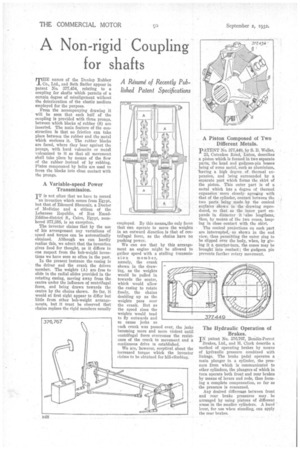
THE names of the Dunlop Rubber Co., Ltd., and Seth Sadler appear in patent No. 377,454, relating to a coupling for shafts which permits of a certain degree of misalignment without the deterioration of the elastic medium employed for the purpose.
From the accompanying drawing it will be seen that each half of the coupling is provided with three Peones, between which blocks of rubber (8) are inserted. The main feature of the construction is that no friction can take place between the rubber and the metal which encloses it. The rubber blocks are faced, where they bear against the prongs, with hard vulcanite or metal vulcanized to it so that all movement shall take place by means of the flow of the rubber instead of by rubbing. Plates compressal by bolts are used to force the blocks into close contact with the prongs.
A Variable-speed Power Transmission.
IT is not often that we have to record
an invention which comes from Egypt, but that of Edouard Shoueair, a Doctor of Medicine and a citizen of the Lebanese Republic, of Rue EmadEddine-district S., Cairo, Egypt, numbered 377,388, is an exception.
The inventor claims that by the use of his arrangement any variations of speed and torque can be automatically obtained. Although we can hardly realize this, we admit that the invention gives food for thought, as it differs in one respect from the bob-weight inventions we have seen so often in the past.
In the present instance the casing is the driver and the crank the driven member. The weights (A) are free to slide in the radial slides provided in the rotating casing, moving away from the centre under the influence of centrifugal force, and being drawn towards the centre by the chains shown. So far, it would at first sight appear to differ but little from other bob-weight arrangements, but it must be observed that chains replace the rigid members usually employed. By this meana,the only force that can operate to move the weights in an outward direction is that of centrifugal force, as the chains have no pushing power.
We can see that by this arrangement an engine might be allowed to gather speed with a stalling transmission member, namely, the crank shown in the drawing, as the weights would be pulled in towards the centre, which would allow the casing to rotate freely, the chains doubling up as the weights pass over the crank. But as the speed rises the weights would tend to fly outwards and so cause jerks as each crank was passed over, the jerks becoming more and more violent until centrifugal force overcomes the resistance of the crank to movement and a continuous drive is established.
We are, however, sceptical about the increased torque which the inventor claims to be obtained for hill-climbing.
A Piston Composed of Two Different Metals.
PATENT No. 377,44e, by S. B. Weller,
22, Cutenhoe Read, Luton, describes a piston which is formed in two separate parts, the head and gudgeon-pin bosses being of some metal, such as aluminium, 'having a high degree . of. thermal expansion, and being surrounded by a separate part which forms the skirt of the piston. This outer part is of a metal which has a degree of thermal. expansion more closely agreeing with that of the cylinder, contact between the two parts being' made, by the conical surfaces shown in the drawing reproduced, so that tes the inner part expands in diameter it .'also lengthens, thus, by mean's of the.two cones, keeping in close contact with the skirt.
The conical projections on each part are interrupted,as shown in the end view, thus permitting the outer ring to be slipped over the body, when, by giving it a, quarter-turn, the cones may be brought into Contact; the gudgeon pin prevents further rotary movement.
The Hydraulic Operation of Brakes.
IN patent No. 376,767, Bendix-Perrot Brakes, Ltd., and H. Clark describe a method of operating brakes by means of hydraulic pressure combined with linkage. The brake pedal operates a main plunger in a cylinder, the pressure from which is communicated to other cylinders, the plungers of which in turn operate both front and rear brakes by means of levers and rods, thus forming a complete compensation, so far as the pressure is concerned.
Any desired difference between front and rear brake pressures may. be arranged by using pistons of different areas in the smaller cylinders. A hand lever, for use when standing, can apply the rear brakes.