


A Water cooled Brake
Page 68
If you've noticed an error in this article please click here to report it so we can fix it.
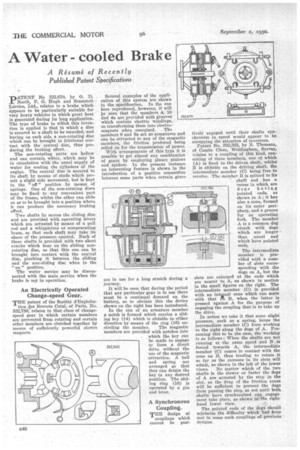
A Resume. of Recently Published Patent Specifications PATENT No 332,670, by 0. D. North, P. G. Hugh and Scainmell Lorries, Ltd., relates to a brake which appears to be particularly suitable for very heavy vehicles in which great heat is generated during its long application. The type of brake to which this invention is applied is that in which a disc is secured to a shaft to be retarded, and having on each side a non-rotating disc which can be brought in frictional contact with the central disc, thus producing the braking effect.
The non-rotating parts are hollow and can contain wtiter, which may be in circulation with the usual supply of water for cooling the cylinders of the engine. The central disc is secured to its shaft by means of studs which permit a slight side movement, but is kept in the " off " position by means of springs. One of the non-rotating discs may be fixed to any convenient part of the frame, whilst the other can slide so as to be brought into a position where it can produce the necessary braking effect.
Two shafts lie across the sliding disc and are provided with operating levers which are actuated by means of a pull rod and a whippletree or compensating beam, so that each shaft may take its share of the pressure exerted. Each of these shafts is provided with two short cranks which bear on the sliding nonrotating disc, so that this one can be brought into contact with the central disc, pinching it between the sliding and the non-sliding disc when in the " on " position.
The water service may be disconnected with the main service when the brake is not in operation.
An Electrically Operated Change-speed Gear.
THE patent of the Societe d'Exploita tion des Brevets Cotal, of Paris, No. 332,789; relates to that class of changespeed gear in which certain members are prevented from rotating and certain other members are clutched together by means of sufficiently powerful electro magnets. Several examples of the application of this system are shown in the specification. In the one here reproduced, however, it will De seen that the members 4, 10 iind 4a are provided with grooves which contain electric whidings, so transforming them into electro magnets when energized. The members 9 and 9a act as armatures and can be attracted to any of the Magnetic members, the friction produced .being relied on for the transmission of power.
With arrangements of this type it is possible to get almost any combination of gears by employing planet pinions and spiders. In the present instance an interesting feature is shown in the introduction of a positive connection between some parts when certain gears are in use journey. for a long stretch during a It will be seen that during the period that any particular gear is in use there must be a continual demand on the battery, so to obviate this the device shown on the right has been introduced.
In the rim of an armature member a notch is formed which carries a sliding key (14) which is slidable in either direction by means of the ring (16) en circling the member. The magnetic members are provided with notches into which the key can be made to engage to form a direct drive without the use of the magnetic attraction. A ball and spring are arranged so that they can detain the key in any desired position. The sliding ring (16) is operated by a pin and lever. tively engaged until their shafts synchronize in speed would appear to be occupying the attention of inventors.
Patent No. 332,302, by B. Thomson, of Combe Close, Weldingliam, Surrey, relates to a coupling of this kind, consisting of three members, one of which (A) is fixed to the driven shaft, whilst B is slidable on the driving shaft, the intermediate member (C) being free to revolve. The member B is splined to its
shaft and has a •
reCess in which are 352.789 dogs having
pointed ends, as shown in A; it has also a cone, formed on its outer periphery, and a groove for an operating fork. The member A is a common dog clutch with dogs which are longer than usual and which have pointed ends.
The intermediate member is provided with a number of slots corresponding with the dogs on A, but the slots are enlarged at the ends which are nearer to A, as shown in section in the small figures on the right. The intermediate member (C) is provided with an intarnal cone which can mate with that d'h B, when the latter is pressed against A. for the purpose of engaging the coupling that is to take up the drive.
In action we take it that some slight pressure, such as a spring, keeps the intermediate member (C) from working to the right along the dogs of A. Presuming this to be the case, the working is as follows : When the shafts are not running at the same speed and B is forced towards A, the intermediate member (C) comes in contact with the cone on B, thus tending to rotate it so far as the recesses in its slots will admit, as shown in the left of the lower views. No matter which of the two shafts is the slower or faster the dogs of A are arrested by the step in the slot, as the drag of the friction cones will be sufficient to prevent the dogs from passing the step, so not until both shafts have synchronized can engagement take place, as shown in-the righthand lower view.
The pointed ends of the dogs should minimize the difficulty which had been met in some such couplings of previous designs.