


The Mass Production of
Page 54
Page 55
Page 56
Page 57
If you've noticed an error in this article please click here to report it so we can fix it.
BALL AND ROLLER BEARINGS
ailed Description of the Methods Employed by the Ransome and Bearing Co., Ltd., in the Manufacture of Bearings for Motor Vehicles
THERE is hardly any branch of the motorcomponent industry which is more interesting than is that concerned with the manufacture of ball and roller bearings, and when one realizes that each part of these bearings calls for the highest possible accuracy, so far as dimensions are concerned, and that the chemical content and method of heat
treatment require the services of thoroughly trained scientists, the ball or roller bearing may be considered as perhaps the cheapest product in the world.
Were such parts as form the components of ball bearings produced by ordinary methods, the balls alone would cost, probably, a guinea each, and the rings would be proportionately expensive.
Although all the processes involved in the manufacture of such bearings are of interest, the making of the ball of high-grade steel, hardened, tempered, ground to a fine limit of sphericity and diameter, and polished to a looking-glass finish, is probably the most interesting of all the operations, so we propose first to describe this and then to outline the making of other parts, ganging, etc.
By kind permission of the Raiasome and Marles Bearing Co., Ltd., we were enabled to inspect the company's well-equipped works at Newark, and to give a detailed description of the methods employed there.
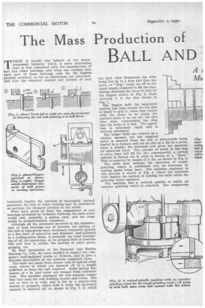
The balls are made from drawn rods of special alloy steel, pieces of which are sheared off to a length sufficient to form the ball required. Balls having diameters of 4 in. and under are formed from cold-steel rods. The machine employed for this purpose resembles that used for cold heading screws and rivets. The rod or wire is in coils, and is fed by a step-by-step motion to grippers, which hold it while the necessary amount is sheared off, as shown in Fig. 1, in which
the first view illustrates the wire being fed up to a stop and then the piece, or "slug," being cut off to the exact length required to fill the dies. During shearing the piece is held by the fingers shown in Fig. 2, these carrying it to the dies shown in Fig. 1.
The fingers hold the separated portion just long enough for the dies to begin to grip it, when they return with the shear to be ready for another piece to be cut off; the dies then close, compressing the slug into the form of a ball. The operation is extremely rapid and is entirely automatic.
The larger balls are treated in a similar manner, but the required metal is sheared from the rod, it afterwards being heated in a furnace and set on end on a die in a press, when a similar die descends and gives the material its spherical form. The amount of metal in the slug is more than will fill the die; consequently, a certain aniount is forced out in what is known as a "flash." This is removed by means of a die, as shown in Fig. 6.
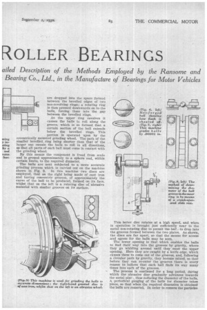
The balls then undergo the operation of roughgrinding, which is performed dry, no lubricant or cooling agent being used.. The machine employed in this process is shown in Fig. 4, where the sectional view depicts the method of holding the balls while the grinding wheel operates.
The machine has a vertical spindle to which an annular grinding wheel is attached. The components are dropped into the space formed between the bevelled edges of two non-revolving rings; a rotating ring is then pressed downwards on to the balls, forcing them into the gap between the bevelled rings.
I I La:: I
As the upper ring revolves it causes the balls to roll along the groove, which is so formed that a certain section of the ball extends below the bevelled rings. This portion is operated upon by the eccentrically mounted grinding wheel. The path of the smaller bevelled, ring being shorter than that of the larger one causes the balls to roll in all directions, so that all parts of each ball must come in contact with the grinding wheel.
By this means the component is freed from scale and is ground approximately to a sphere and, within certain limits, to the required diameter.
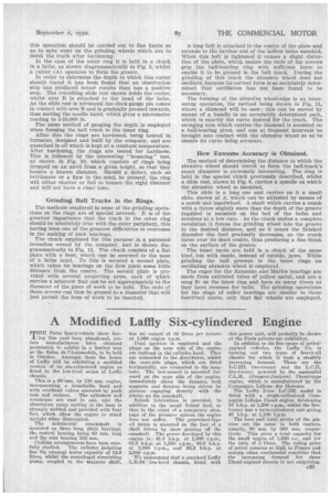
The balls are next subjected to a more accurate grinding process which is carried out on the machine shown in Fig. 9. In this machine two discs are employed, that on the right being made of cast iron and having concentric grooves, of approximately the curve of the ball to be produced, formed on its face, whilst that on the left is a rotating disc of abrasive material with similar grooves on its surface. This latter disc rotates at a high speed, and when in operation is brought just sufficiently near to the metal non-rotating disc to permit the bat!, to drop into the grooves formed between the two plates. As shown, the discs are far apart, so that the means for access and egress for the balls may be seen.
The lower opening is that which enables the balls to find their way into the grooves by gravity, where they go whirling around until they meet the upper opening. Here they are caught by a knife edge, which causes them to come out of the grooves, and, following a circular path by gravity, they become mixed, so that before they can re-enter the grooves there is every reason to believe that each hall finds its way many times into each of the grooves.
The process is continued for a long period, during which the abrasive disc gradually advances towards the metal plat thus reducing the diameter of the balls. 'A periodical gauging of the balls for diameter takes place, so that when the required dimension is obtained the balls are removed. In order to remove the particles
of metal ground off the conwonents a lubricant, such as paraffin, is used during this process. In this machine an enormous number of balls is dealt with at a time.
After this grinding the balls are hardened by being gradually heated in a rotating furnace, where they are carried along by means of an internal helical flange until they are discharged into a tank of water, which is kept at a constant temperature. On completion of this operation the balls are tempered in heated oil, an inspection for hardness being carried out on each batch by crushing a certain number.
Having passed this test the balls are ready for the process of lapping, which consists of a finer grinding in a machine similar to that shown in Fig. 9, but with a much finer grade of abrasive disc and more careful gauging for diameter.
From this stage the balls go to the barrelling operations, which consist of placing them in a rotating cylinder, first with various grades of abrasive and polishing substance and finally with nothing but cuttings of wash-leather, which give the looking-glass polish necessary for the working of bearings.
A visual inspection follows and is particularly interesting. The balls are placed in a shallow tray, this tray being held by an inspector, so that the balls rest against the edge farthest from the operator. The upper portions of the balls reflect light from the roof, but the inspector does not look at these parts; she examines the bower halves, which have reflected in them the white paper at the bottom of the tray. ,
As she looks at the row of balls, which are rolled slowly along, the practised eye is able to detect flaws or blemishes, which to the untrained observer would be indiscerrtable. Minute defects in the steel, known as "hair-lines," are instantly detected. Soft spots have a degree of polish different from that of the fully hardened parts, and any defective ball is removed. Fig. 11.—The the edge of an means of a diam a circ The Gauging of Steel Balls.
After this the balls are gauged in an automatic machine, a diagrammatic sketch of which will be seen in Fig. 7. Two hardened-steel straight-edges are placed at a slight angle with one another, and are set at such a tilt that balls will roll down the gap between them. The narrowest part of the opening is at the higher end, so that as a ball rolls down it drops through the gap, when it reaches a part that corresponds with its diameter.
A series of eight partitions is situated below the gap, so that as the balls pass along they automatically sort out themselves. Six of the eight barriers are within the limits of usefulness, whilst the two end ones are for rejects that are either too large or too small.
Further grading is carried out under a minimeter. The balls are marked off into batches varying by .00002 in.; the minimeters are set by master balls calibrated by the National Physical Laboratory.
c34
As thecompany, the methods of which we are describing—Ransome and Merles Bearing Co., Ltd.— does not usually manufacture bearings with taper rollers, we must confine ourselves to the making of parallel roller bearings. The processes of producing these rollers do not differ considerably from those of balls, so do not call for any detailed description. They are cut from a rod, ground in centreless grinders and finally lapped to a looking-glass polish between metal discs.
The progress made in recent years in the manufacture of alloy steels has rendered the process of casehardening practically obsolete for high-grade-bearing production, for balls, rollers and rings.
How the Rings are Made.
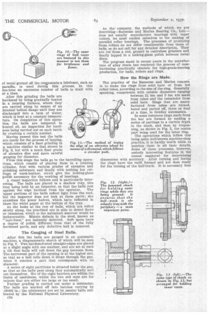
The practice of the Ransome and Marles concern is to make the rings from solid bars or from hot rolled tubes, according to the size of the ring. Generally speaking, components with outside diameters ranging between 21 ins. and 5 ins, are made from tubes and the remainder from solid bars. Rings that are manufactured from tubes are turned, bored and parted off, three or four at a time, in Gridley automatics.
In some instances rings made from the bar are formed by making a series of partings to a certain depth in the stock, and then by trepanning, as shown in Fig. 5, the centre part being used for the inner ring.
The operations which follow this being quite well-known machine-shop practice, it is hardly worth while to mention them in all their details. Some of these processes, however, embody interesting features in the
' means employed for determining dimensions with accuracy. After turning and boring the rings have the radii formed and are then ready for the turning of the ball-track. It is necessary that
this operation should be carried out to fine limits so as to save wear on the grinding wheels which are to finish the traCk after hardening.
In the case of the outer ring it is held in a chuck In a lathe, as shown diagrammatically in Fig. 3, whilst a cutter (A) operates to form the groove.
In order to determine the depth to which this cutter should travel it has been found that an observation stop has produced better results than has a positive stop. The travelling slide rest shown holds the cutter, whilst arm B is attached to the head of the lathe. As the slide rest is advanced the clock-gauge pin comes in contact with arm B and is gradually pressed inwards, thus moving the needle hand, which gives a micrometer reading to 1-10,000 in.
The same method of gauging the depth is employed when forming the hall track in the inner ring.
After this the rings are hardened, being heated in furnaces, designed and built by the company, and are quenched in oil which is kept at a constant temperature. After hardening, the rings are tested for hardness. This is followed by the interesting " bouncing " test, as shown in Fig. 10, which consists of rings being dropped on an anvil from a given height, so that they bounce a known distance. Should a defect, such as brittleness or a flaw in the steel, be present, the ring will either shatter or fail to bounce the right distance and will not have a clear tone.
Grinding Ball Tracks in the Rings.
The methods employed in some of the grinding operations on the rings are of special interest. It is of the greatest importance that the track in the outer ring should be absolutely true with the outer periphery, this having been one of the greatest difficulties to overcome in the making of such bearings.
The chuck employed for this purpose is a patented invention owned by the company, and is shown diagrammatically in Fig. 12. The chuck consists of a flat plate with a boss, which can be screwed to the nose of a lathe head. To this is secured a second plate, which takes its bearings on the first plate some little distance from, the centre. The second plate is provided with several projecting arms, each of which carries a setscrew that can be set approximately to the diameter of the piece of work to be held. The ends of these screws can then be ground to a diameter that will just permit the item of work to be inserted. A long bolt is attached to the centre of the plate and extends to the farther end of the hollow lathe mandrel. When this bolt is tightened it causes a slight distortion of the plate, which makes the ends of the screws grip the ball-hearing ring with sufficient force to enable it to be ground in the ball track. During the grinding of this track the abrasive wheel does not oscillate, because itS correct form is so accurately determined that oscillation has not been found to be necessary.
The forming of the abrasive wheel-edge is an interesting operation, the method being shown in Fig, 11, where a diamond will be seen ; this can be moved by means of a handle in an accurately determined path, which is exactly the curve desired for the track. The swinging arm which carries the diamond is mounted on a ball-bearing pivot, and can at frequent intervals be brought into contact with the abrasive wheel so as:10 ensure its curve being accurate.
How Extretfte Accuracy is Obtained.
The method of determining the distance to which the abrasive wheel should travel to form the ball-track's exact diameter is extremely interesting. The ring is held in the special chuck previously described, whilst a slide rest, shown in Fig. 8, carries a spindle on which the abrasive wheel is mounted.
This slide is a long one and carries on it a small slide, shown at A, which can be adjusted by means of a sere* and handwheel. A shaft which carries a crank with a throw slightly more than the depth of the groove required is mounted on the bed of the lathe and revolves at a low rate. As the crank makes a complete revolution it forces the grinding wheel into the groove to the desired distance, and as it nears the finished diameter the feed gradually decreases, as the crank turns over its dead centre, thus producing a fine finish on the surface of the groove.
The inner, races are held in a chuck of the same kind, but with inside, instead of outside, jaws. While grinding the ball grooves in the inner rings an oscillating abrasive wheel is employed.
The cages for the Ransorne and Marles bearings are made from extruded tubes of yellow metal, and are a snug fit on the inner ring and have as many rivets as they have recesses for balls. The grinding operations for the rings of roller bearings are similar to those described above, only that flat wheels are employed.