


Patents Completed.
Page 20
If you've noticed an error in this article please click here to report it so we can fix it.
Complete specifications of the following patents will be sent to any address in the United Kingdom upon receipt of eightpence per copy at the Sale Branch, Patent Office, Holborn, W.C.
VALVE GEAR.---13cillee.—No. 9844, of 1911, dated under Convention, 3rd April, 1910.—In gear for the operation of valves it is desirable to leave a certain amount of play in the motion to ensure airtight closing of the valve during its period of rest. If this play be not
allowed, it is necessary for the valves to fit on the seat and for the roller to fit on the cam so exactly that frequent and careful a.djustment will be necessary. In internal-combustion engines, where such play is allowed, there results a considerable amount of noise, and the valves are worn more than they should he. According to the present invention this play is automatically regulated so that it is kept at at minimum value without being ennipleteiy suppressed which would prevent the valves closing in an air-tight manner. In the valve-rod pusher there is interposed a piston arid cylinder containing a liquid. A small spring-controlled valve allowsthe passage of the fluid from one side of the piston to the other, The main valve spring constantly tends to compress the fluid under the piston and to drive it out by leakage. A weaker spring acti upon the piston in the opposite direction_ The effect of this construction is that the play is reduced very considerably, the actual amount depending on the adjustment of the springs and the density of the lienid. etc.
HYDRAULIC CHANGE SPEED GEAR.—Stokes.—No. 11,561, dated 12th May, 1911.—The change-speed gear described in this specification is of the type wherein one member carries a number of radially-disposed cylinders adapted to contain oil or other liquid. and the other member carries a crank to which is connected a number of pistons working in the cylinders and cir culating the liquid between the cylinders. The present invention liea in the simple construction wherein the liquid is confined in channels which are disposed laterally in the axial plane of the cylinders. These channe3s lead to the valve by which control is effected. There is thus no necessity to use the ordinary floating transmission ring encircling the cylinders, which form of construction increases the friction there considerably. There is also described and illustrated in detail a duplex valve for controlling the flow of liquid. The valve comprises two members, the inner one of which controls a through port, while the outer member opens an unrestricted port to allow the flow of liquid, and thereby prevents any possible throttling when the no-clutch action is desired between the members.
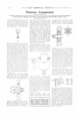
LAMP BRACKET.—Camelinat.—No. 21,760, dated 20th September, 1910.— This invention relates to lamp brackets for motor vehicles, and is especially intended to allow adjustment of the lamp to throw the brain of light either far ahead or upon the erolind immelliately in
front of the veil lc.. The fittims comprises a screwed bolt or shank attached to the lamp body and passing through the lamp fork or bracket. The inner surface of this part is serrated, and the teeth thereon engage with corresponding teeth upon the movable part of the lamp. As previously constructed, fittings like this have had the teeth locked together by means of a spring. ln this case, however. the locking parts are taken into direct engagement by the action of the nut, so that a positive lock is obtained, and the lamp can only he adjusted by slacken inn the nut,
SPRING WHEEL. — Moser. — No. 28.979 of 1910. Date. claimed under Convention 15th January, 1910.--In this specification there is described a shockabsorbing wheel, of the type in which spherical bodies or balls made of hard metal are enclosed within displaceable
chambers; they act as a fluid therein. The characteristic feature of this wheel is that the chambers in which the balls are contained are entirely filled with balls, and that these chambers are formed with internal ribs or projections or are so shaped that the balls are carried round as the chamber rotates. In the Preferred construction, the wheel comprises one or more centrally-movable concentric chambers, enclosed between parallel plates placed concentrically on the axle. A further feature of the invention lies in the fact that the inner wall of the chamber lying between the two parallel plates is made to revolve with the wheel by an arrangement of keys, which engage with two recesses in the elates.
HYDRAULIC-TRANSMISSION MECHANISM.-Rich.—No. 10,007, dated 25th April, 1911.—This invention comprises a complete hydraulic-trensmission mechanism for automobiles, of the type wherein fluid is forced by means of a
pump driven by the motor engine to a fluid-operated motor which is adapted to transmit. power to the driving wheels of the vehicle. An ordinary rotary fluidpressure motor is used, and the particular feature nf the invention lies in the controller. This comprises a valve having on its periphery a number of passages adapted to establish communication between the intake and discharge openings of the pump and the separate communication between the intake and discharge openings Of the motor, These passages are formed transversely, diagonally and parallel according to the driving requirements of the motor for speed, reversing, etc.