


MORE RAPIDITY IN LOADING.
Page 12
Page 13
Page 14
If you've noticed an error in this article please click here to report it so we can fix it.
Some New Devices Suggested for Use in Particular Circumstances in Order to Economize Time at Terminals.
IN THESE days of high-priced labour, it is as well to consider what can be done to economize cost . of transport by saving time at both ends of a jourhey. On many short journeys, the time spciat in loading and unloading is out of all proportion to the total time of the job.
Many a concern faced with the costs of its transport. system, and finding them compare not so favourably as had been expected with the costs of its former system based upon horse-drawn vehicles, has called in expert assistance, and we have had the opportunity arid privilege of scanning some of the reports that
have resulted. In the vast majority of cases the expert has been able to point out that the merits of the motor vehicle have not been allowed to be demonstrated.
With a slow-going vehicle, the time occupied on the return journey in actual travelling is obviously in a higher proportion to the time spent in loading and unloading, than is the case when the time on the journey is cut down, as in the case of a faster vehicle to, say, one half. Thus, the evil shows up in an aggravated form in thie case of the motor vehicle, and there is naturally a desire, once they have been discovered, to secure the elimination of the faults in the system. But, despite the fact that the faults are gradually being recognized, means for avoiding them are not to be procured so easily. Above all things, whatever may he the scheme which is adopted, it must be practical -and be based upen experience, otherwise the last state of the concern adopting it will be worse than the first if only because of the prejudice it is lik'ely to cause among those called upon to operate it.
We propose in this article to describe some of the newest ideas in loading and unloading, not attempting to go over the old ground and the more liackney'ed method's. The latter will all be known to our readers, but we venture to think that in the following notes something new in loading and unloading devices will be discovered.
To deal first of all with side unloading, which is less resorted to than one would expect. In many cases unloading at the back is not so convenient as side unloading, as, when the vehicle has to go up a narrow passage it is not posaible for it to back out until the load which has been taken off at the rear has been removed from its path. Another thing which should be considered is that it is not always possible to arrange the loading so that the goods which have to be unloaded first shall be the I:earl/lost.
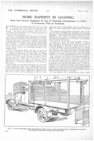
Fig. 1 shows a lorry fitted with a light steel gantry, which will allow any parcel or goods to be removed at either side or at the *az, as desired. Cranes are not always available, and are often non-existent, and, in such cases the driver has either to get help, or, if possible, take the load -off bit by bit. It will be seen from an examination of Fig. 1 that there are six uprights to the gantry, and that they are connected at the front, centre, and rear by cross-mentlYers. Two long members extend over the top from the front to slightly beyond the rear of the body.
A cross-member (A) is mounted on shoes, with rollers so that it can easily be moved from front to rear. The length of A is such that it can pass between the upright members, and can be drawn out at
the rear, as shown in dotted lines. Beneath A is another beam (C) exactly similar to A in length and section. A carriage (B) -with rollers, as shown, connects A and 0 in such a way that C can be extended at either side, as shown in Figs. I and 2.
It should be noted that the carriage B is merely hooked round the edges of beam C, so that the latter can be moved right across.
A carriage (D), carrying a worm-actuated chain gear, of suitable lifting poWer for the load to be carried, is provided, which should be swivelled so that the hand-chain can be brought into a convenient position for handling on either side, or at the rear. By this means, any part of the load can be removed, as indicated in Fig. 3,and deposited in any desired position.
Lift Trucks and Platforms.
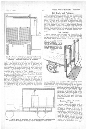
For certain classes of goods, the use of platforms and the special trucks for lifting and transporting them saves a great deal of handling. Figs. 1 and 2 show platforms with sides and hooks for lifting. These, if fitted with rings and in conjunction with a beam (E), Fig. 2, can be lifted with great ease and left with their loads on them ready to be transported by a lift -truck at any time. This method enables goods of certain classes to be brought from the actual source of production to the lorry, and, when deposited elsewhere, to be carried to an desired place with the actual minimum of manual labour and cost.
Tail Loading.
Where loading from the tail only is needed, the device shown in Fig. 4 is useful. It consists of two upright members of channel steel attached to the body and stayed at the back. They are connected across the top by a member. This member should overhang to the extent of half the width of the loads to be carried. Two chains, spreading at the bottom, support a steel plate, which should be as thin as Possible consistent with the load to be carried, so that wheeled trucks can easily be rolled on to it. This plate can be hinged to the guides (F) so that when not in use it can form a tailboard. Here, again, the use of lift and platforms, where convenient, will save. much handling.
Loading Piles of Goods En bloc.
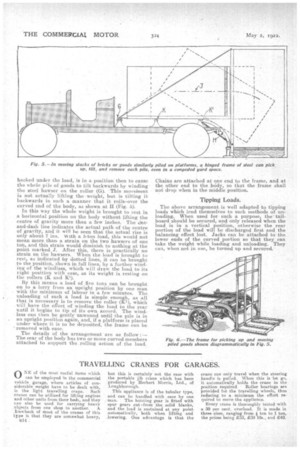
Many classes of goods, such as bricks, etc., are stacked in piles approximately 8 ft. high, covering an area of about 4 ft. by 4 ft. In such cases, if the pile of goods is stacked on a platform, as shown in Fig. 5, which allows a clear space unolernewth it, it is possible to load the -whole lot in one block with the device shown. A frame of steel, with horizontal members, which can easily pass under the platform, is provided, and, when
backed under the load, is in a position then to cause the whok pile of goods to tilt backwards by winding the steel hawser on the roller (G). This movement is not actually lifting the weight, but is tilting it backwards in such a manner that it rolls-over the curved end of the body, as shown at II (Fig. 5).
In this way the whole weight is brought to rest in a horizontal position on the body without lifting the centre of gravity more than a few inches. The dotand-dash line indicates the actual path of the centre of gravity, and it will be seen that the actual rise is only about 7 ins. with a 5-ton load, this would not mean more than a strain on the two hawsers of one ton, and this strain would diminish to nothing at the point marked J. After this, there is practically no strain on the hawsers. When the load is brought to rest, as indicated by dotted lines, it can he brought to the position, shown in full lines, by a further winding of the windlass, which will draw the load to its right position with ease, as its weight is resting ott the rollers (K and RI).
By this means a load of five tons can be brought on to a lorry from an upright position by one man with the minimum of labour in a few minutes. The unloading of such a load is simple enough, as all that is necessary is to remove the roller (K1), which will have the eitect of winding the load to the rear until it begins to tip of its own accord. The windlass can then be gently unwound until the pile is in an upright position again, and, if a platform is placed under where it is to be deposited, the frame can be removed with ease.
The details of the arrangement are as follow :— The rear of the body has two or more curved members attached to support the, rolling action of the load. Chains are attached at one end to the frame, and at the other end to the body, so that the frame shall not drop when in the middle position.
Tipping Loads.
The above arrangement is well adapted to tipping loads which lend themselves to such methods of unloading. When used for such a purpose, the tailboard should be secured, and only released when the load is in a vertical position, otherwise the rear portion of the load will be discharged first and the balancing effect lost. Jacks can be attached to the lower ends of the curved portion so that they can take the weight while loading and unloading. They can, when not in use, be turned up and secured.