


An Oil-cooled Piston for Oil Engines
Page 64
If you've noticed an error in this article please click here to report it so we can fix it.
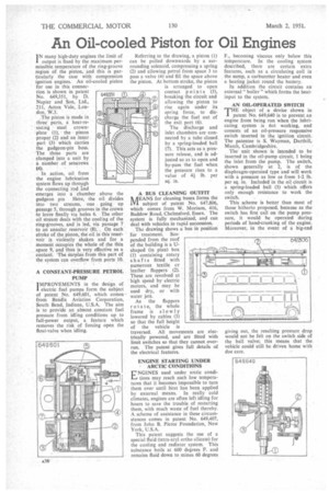
I N many high-duty engines the limit of output is fixed by the maximum permissible temperature of the ring-groove region of the piston, and this is particularly the case with compression ignition engines. An oil-cooled piston for use in this connection is shown in patent No. 649,351, by D. Napier and Son, Ltd., 211, Acton Vale, London, W.3.
The piston is made in three parts, a heat-resisting steel crownplate (1), the piston proper (2) and an inncr part (3) which carries the gudgeon-pin boss. The three parts are clamped into a unit by a number of setscrews (4).
In action, oil from the engine lubrication system flows up through the cqnnecting rod rind emerges into a chamber above the gudgeon pin Here, the oil divides into two streams, one . going up passage 5, through grooves in the crown to leave finally via holes 6. The other oil stream deals with the cooling of the ring-grooves, and is led, via passage 7 to an annular reservoir (8). On each stroke of the piston, the oil in this reservoir is violently shaken and for a moment occupies the whole of the thin space 9, and thus is very effective as a coolant. The surplus from this part of the system can overflow from ports 10.
A CONSTANT-PRESSURE PETROL PUMP
I MPROVEMENTS in the design of electric fuel pumps form the subject of patent No. 649,601, which comes from Bendix Aviation Corporation, South Bend, Indiana, U.S.A. The aim is to provide an almost constant fuel pressure from idling conditions up to full-power output, a feature which removes the risk of forcing open the float-valve when idling.
Referring to the drawing, a piston (1) can be pulled downwards by a surrounding solenoid, compressing a spring (2) and allowing petrol from space 3 to pass a valve (4) and fill the space above the piston. At bottom stroke, the piston is arranged to open contact points (5), breaking the circuit and allowing the piston to rise again under its spring force, to discharge the fuel out of the exit port (6).
The discharge and inlet chambers are connected by a tube closed by a spring-loaded ball (7). This acts as a pressure release, and is adjusted so as to open and by-pass the fuel when the pressure rises to a value of 4i lb. per sq. in.
A BUS CLEANING OUTFIT
MEANS for cleaning buses forms the subject of patent No. 647,806, which comes from W. Morison, 416, Baddow Road, Chelmsford, Essex. The system is fully mechanized, and can deal with vehicles in rapid succession.
Tbe drawing shows a bus in position for treatment. Sus pended from the roof of the building is a Ushaped (in plan) box (1) containing rotary shafts fitted with numerous textile or leather flappers (2). These are revolved at high speed by electric motors, and may be used dry, or with water jets.
As the flappers rotate, the whole frame is slowly lowered by cables (3) so that the full height of the vehicle is traversed. All movements are electrically powered, and are fitted with limit switches so that they cannot overrun. The patent gives full details of the electrical features.
ENGINE STARTING UNDER ARCTIC CONDITIONS NGINES used under arctic condi tions may reach such low temperatures that it becomes impossible to turn them over until heat has been applied by external means. In really cold climates, engines are often left idling for hours to save the trouble of restarting them, with much waste of fuel thereby. A scheme of assistance in these circumstances comes in patent No. 649,407, from John B. Pierce Foundation, New York, U.S.A.
This patent suggests the use of a special fluid (tetra-aryl ortho silicate) for the cooling and radiator system. This substance boils at 600 degrees F. and remains fluid down to minus 60 degrees F., becoming viscous only below this temperature. In the cooling system described, there are certain extra features, such as a circulating coil in the sump, a carburetter heater and even a heating jacket round the battery. In addition the circuit contains an external " boiler " which forms the heatinput to the system.
AN OIL-OPERATED SWITCH
THE object of a device shown in patent No. 649,640 is to prevent an engine from being run when the lubricating system is not working, and consists of an oil-pressure responsive switch inserted in the ignition circuit. The patentee is S. Wayman, Darthill, March, Cambridgeshire.
The unit shown is intended to be inserted in the oil-pump circuit, I being the inlet from the pump. The switch, shown generally at 2, is of the diaphragm-operated type and will work with a pressure as low as from 1-2 lb. per sq. in. Included in the oil circuit is a spring-loaded ball (3) which offers only enough resistance to work the switch.
This scheme is better than most of those hitherto proposed, because as the switch has first call on the pump pressure, it wouldbe operated during periods of hand-cranking of the engine. Moreover, in the event of a big-end
giving out, the resulting pressure drop would not be felt on the switch side of the ball valve; this means that the vehicle could still be driven home with due care.