


CREEPER TRACK PROGRESS.
Page 14
Page 15
If you've noticed an error in this article please click here to report it so we can fix it.
Details of a Light Crossley Model of 14 h.p. Developed for Military Purposes.
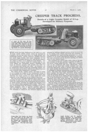
MILE horse has been displaced on the road to a very
large extent within "recent years by mechanical transport, but he has held sway on virgin ground and undulating country. Lately, however, roadless traction has made rapid strides, and when companies of the importance of Crossley Motors, Ltd. take up the cudgels, the horse is likely to be displaced even further. Undoubtedly there is great scope for vehicles able to traverse almost any reasonable surface, including such Items Fi's ditches, mounds, soft ground, etc., both for civic purposes and during war time. An ordinary car or commercial vehicle would get hopelessly bogged, but the latest types of trackless vehicles are able to traverse such surfaces with comparative certainty.
The object of the "girder track," for such it really is, is to enable the weight of the vehicle as a whole to be distributed over a very large area, at the same time allowing the bogie portion to adapt itself for track adhesion to the exigencies of the country traversed. The new 14 h.p. Crossley Kegresse has a capacity for carrying 15 cwt. to 20 cwt., and, by virtue of the essentially low construction of the framework and the absence of Wheel arches, provides an equally low loading level for the vehicle when equipped with a body. The power unit IS developed from the pOpular Crossley 14 h.p. car engine equipped with a special gearbox 'mounted unit-wise with the engine. Three-point suspension for this assembly is employed, the forward support being obtained by bolting a flanged portion of the forward end of the timing cover (which surrounds the extension of the crankshaft for hand-starting purposes), to a crossmember of the frame immediately behind the radiator. The rear extensions of the flywheel' housing are bolted direct to the chassis frame:
The cylinders are cast en bloc, with a bore of 80 mm. and a stroke of 120 mm., giving a capacity of 2,388 c.c.. the R.A.C. rating being 15.6 h.p. They are a separate unit to the crankcase and have side-by-side valves situated on the near side, totally enclosed and autoinatically lubricated, whilst a quickly detachable cylinder head enables decarbonization or valve grinding to be attended to without dismantling of a large number of parts. The inlet and exhaust manifolds are in a onepiece casting, the inlet pipe, therefore, being heated from the exhaust manifold. The exhaust lead is taken away at the front of the engine and thus excessive heating of the floorboards is avoided. The crankshaft and camshaft have each three bearings, the former being fed by oil under pressure, thence by drilled passages to the big-end bearings of the connecting rods.
The oil pump is of the plunger type, driven from the camshaft, a relief valve being incorporated in the pump body. A gauge is included in the system and is located • on the instrument board, whilst a gauge denoting the quantity of oil in the sump is bolted direct to the near side of the sump casing close to the depression for the
pump and filter, access to the latter being obtained by removing the plate beneath the pump depression. Both dynamo and electric starter are attached by a flange mounting, the dynamo being positively driven by a triangular timing chain layout. Contrary to usual practice, a roller chain is empleyed, adjustment being provided by swinging out the dynamo mounting. The magneto is driVen in tandem from the dynamo through a Simms vernier coupling which.permita a slight variation in centres-without -ill-effect.
• The 'cooling' water is circulated thermo-siphonically, large-dianieter water cOnnections being provided.' • A single-plate clutch, with fabric friction discs, is totally enclosed by a rearward extension of the crankcase, to the outsid& perimeter of which a four-speed gearbox with Operating lever complete is bolted. The spigot is fitted with a ball bearing and is automatically • lubricated. An inspection door normally covered by a sheet-metal plate permits adjustment of the clutch springpressure and allows the togglearms and thrust race to be inspected and lubricated as required.
Two gearboxes are included, the forward one giving four speeds. The, reductions in this box are 4.61 to 1 first speed, 2.862 to 1 second speed, 1.812' to 1 third speed, and direct on top. Another two-speed gearbox is incorporated on the Keg-resse track .rear axle, which, when used in conjunction with the four-speed box bolted to the elutch, housing, enables gear ratios from 164.9 to 1 to 8.45 to 1 to be obtained. Eight forward speeds are provided and two reverse speeds, so that all conditions of travel are amply catered for. Two gear levers, both mounted on the off side of the chassis., connect through to their respective gearboxes and are conveniently placed for operation, whilst a special differential locking device is also fitted for use on soft ground. By this means, if one track is running upon a stirface where it can obtain a good grip and the other is running in, say, a ditch where its contact with the ground is very poor, hip two-tracks can be locked together so that all the drive is taken through the one side, at the same time
• Preventing the other track spinning.
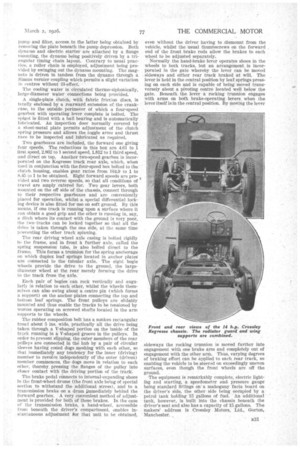
• The rear driving wheel axle casing is bolted rigidly • to the frame, and in front a further axle, called the spring suspension tube, is also bolted direct to the frame. This forms a trunnion for the spring anchorage on which duplex leaf springs located in anchor plates are connected to the tubular axle. The eight bogie wheels provide the drive to the ground, the largediameter wheel at the rear merely forming the drive to the track from the axle.
Each :pair of bogies can rock vertically and angularly in relation to each other, whilst the wheels themselves can also swing about a centre pin (which forms a support) on the anchor plates connecting the topand
• bottom leaf springs. The front pulleys are slidably mounted and thus enable the tracks to be tensioned by worms operating on screwed shafts located in the arm supports to the wheels.
The rubber composition belt has a sunken rectangular tread about 5 ins, wide, practically all the drive being taken through a V-shaped portion on the inside of the track running in a V-shaped groove in the pulleys. In order to prevent slipping, the outer members of the rear pulleys are connected in the hub by a pair of circular sleeves having coned dogs meshing with each other, so that immediately any tendency for the inner (driving) memher to revolve independently of the outer (drivea) member commences, the dogs move in relation to each
• other, thereby pressing the flanges of the pulley into closer contact with the driving portion of the track'. The brake pedal connects to internal-expanding shoes in the front-wheel drums (the front axle being of special section to withstand the .additional stress), and to a transmission brake on a drum i,mmediately behind the forward gearbox. A very convenient method of adjustment is provided for both of these brakes. In the case of the transmission brake, a hand-wheel, accessible from beneath the' driver's compartment, enables in stantaneous adjustment or that unit to be obtained,
even without the driver having to dismount from the vehicle, whilst the usual thumbscrews on the forward , end of the front brake rods allow the brakes to each wheel to be adjusted separately.
Normally the hand-brake lever operates shoes in the wheels to both tracks, but an arrangement is incorporated in the gate whereby the lever can be moved sideways and either rear track braked at will. The lever is held in the central position by leaf springs pressing on each side and is capable of being moved transversely about a pivoting centre located well below the gate. Beneath the lever a rocking trunnion engages with arms on both brake-operating levers when the lever itself is in the central position. By moving the lever
sideways the rocking trunnion is moved farther into engagement with one brake arm and completely out of engagement with the other ani). Thus, varying degrees of braking effort can be applied to each rear track, so enabling the vehicle to be steerod on exceedingly uneven surfaces, even though the front wheels are off the ground.
The equipment is remarkably complete, electric lighting and starting, a speedometer andpressure gauge being standard fittings on' a mahogany facia board on the driver's side, the other side being occupied by a petrol tank holding 15 gallons of fuel. An additional tank, however, is built into the chassis beneath the driver's seat and also has a capacity of 15 gallons. The makers' address is Crossley Motors, Ltd., Gorton, Manchester.