


MODIFYING CHASSIS FOR A SPECIAL CONTRACT.
Page 12
Page 13
If you've noticed an error in this article please click here to report it so we can fix it.
Interesting Alterations to a Standard F.W.D. Chassis in Railway Construction. for Special Work
THE construction ot a railway requires an enormous amount ot virgin ground to be covered in order that tracks may be laid sufficiently hard for the steam plant to traverse, and, in consequence, the conditions imposed upon lorries engaged upon the work are of such a nature that special vehicles are really required. In order to meet these requirements the Anglo-Spanish Construction Co., engaged upon a contract for railway construction in the Peninsula, are using many F.W.D. lorries, and, in particular, six with chassis specially adapted to meet the requirements of such an undertaking. Three have already gone, and when the second three were ready for test a representative of this journal was enabled to view them under actual working conditions.
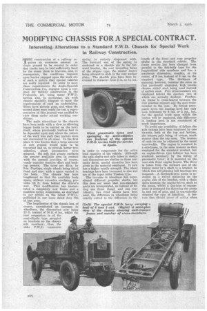
The main alterations to the chassis have been made with a view to allowing bigger loads to be carried on the lorry itself, where previously trailers had to be depended upon and where the nature of the work was such that trailers were not convenient in all cases. In the first place it was known that a large amount of soft ground would have to be traversed and so, to provide better tyr1 adhesion, giant pneumatics were adopted. On soft and greasy surfaces the greater available area in contact with the ground provides, of course, vastly superior tractive effort and braking powers. The tyres are 42-in. by 9-in. Dunlops. single wheels being fitted front and rear, with a spare carried in the body. The chassis has been lengthened so that the available body space, without excessive overhang, provides 16 ft. from behind the driver's seat. This modification has necessitated a completely new frame and a modified spring suspension, as described in our article on the latest F.W.D., published in our issue dated July 7th of last year.
The lengthening of the chassis has, of course, necessitated an increase in wheelbase, the dimensions now being 13 ft. instead of 10 ft. 4 ins., whilst the rear suspension is of the semi-elliptic type mounted on brackets on the chassis side members ; thus, the older F.W.D. transverse spring is entirely dispensed with. The forward end of the spring is anchored on a shackle pin in the forward bracket, the rear mounting being of the slipper type, the master leaves being allowed to slide in the rear anchor plate. The shackle pins have been increased in diameter from in. to I* ins.
in order to compensate for the extra load capacity of the vehicle. Although the axle shafts and axle tubes in design and dimensions are similar to those normally fitted, special attention has been given to the material employed. It now has a higher tensile strength. The wheel bearings have been increased in size and are of the taper roller Timken type.
The increase in wheelbase has necessitated different propeller shafts, but this does not mean that non-standard parts are incorporated, as instead of fitting one front (long) and one rear (short), two front shafts have been . used, the difference in wheelbase being exactly suited to the difference in the length of the front and rear propeller shafts in the standard vehicle. The frame section has been changed from parallel to the fish-belly type for the longitudinal side members and has a maximum dimension, roughly, at its centre, of 9 ins, instead of 5 ins, on the standard type. The thickness of material, however, remains the same as that previously employed, high tensile chrome nickel steel being used instead of carbon steel. Five cross-members are employed behind the gearbox, two of which are actually doubled. Further, the frame is cross-braced between the rear gearbox support and the next crossmember to the rear. By fitting pneumatic tyres the loading level has only been increased by 4 ins. or 5 ins., but, for the special work upon which the lorries will be employed, this difference in loading level is not considered of much importance.
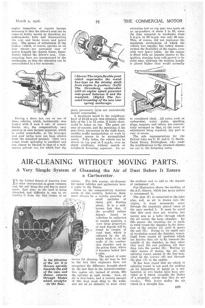
To avoid any possibility of failure the axle casings have been tensioned by two tie-rods, both at the top and bottom, the bottom pair being, of course, much stouter than the top ones. The tension of each tie can be adjusted by the usual turn-buckle. The engine is mounted in a sub-frame, in the same manner as that employed for the standard product, but an engine-driven tyre inflator has been rendered necessary by the fitting of pneumatic tyres; it is mounted on the near-side front engine bearer. The drive is taken from the forward end of the timing cover by a shaft to a bracket, in which two self-aligning ball bearings are mounted. A Norraack-type pump is installed on a swivel mounting on the engine side of the bracket, with a chain drive between the engine-driven shaft to the pump, whilst a dog-type of engagement is arranged for throwing the pump in and out 'of gear, and is conveniently situated for ease of handling. A feature that should prove of utility when
engine inspection or repairs become necessary is that the driver's seat can be removed bodily merely by detaching six holding-down bolts and disconnecting the gear and brake levers and petrol pipe. The means of adjustment of the brakes—which, of course, operate on all four wheels—are extremely easy of access beneath the chassis frame, immediately behind the driver's seat. COMpensating bars are incorporated in the mechanism, so that the operation can be accomplished in a few moments.
During a short test run on one of these vehicles, which, incidentally, was loaded with 6 tons 5 cwt. of cement blocks, etc., the comparatively easy steering at once became -apparent, which is rather remarkable, as the leverages and gear ratios have not been altered from the standard product. Over very rough roads springing is excellent and can almost be likened to that of a wellsprung private car, for which fact the giant pneumatic tyres are undoubtedly largely responsible.
A maximum speed in the neighbourhood of 23-24 m.p.h. was obtained, while hills of the 1 in 12 order, if fairly short, could be taken on top. The gears are easy to operate, and the mounting of the gear lever, convenient to the right hand, enables traffic manipulation or work in confined spaces to he accomplished easily. Fully laden, the vehicle can be driven on top gear at 5 m.p.h., even up slight gradients, without snatch or roughness becoming apparent. An ac
celeration test on top gear was made on an up-gradient of about 1 in 15, when the time occupied to accelerate from 5 m.p.h. to 20 m.p.h. was only 40 secs. This, of course, did not represent the maximum acceleration of which the vehicle was capable, but rather demonstrated the flexibility of the engine, even with very heavy loads. As the engine is fitted with an impulse starter to the ignition, starting from cold proved to be quite easy, although the starting handle is placed higher than would normally be considered ideal. All units, such as carburetter, water pump, sparking, plugs, magneto and valves, are conveniently arranged so that, in the event of adjustment being required, any part is easy of access.
The sole representatives for the British Isles are C. H. and L. 0. Smith, 'Canal Street, Nottingham, who made the modifications to the standard chassis set out in the foregoing notes.