 1
1 2
2 3
3 4
4 5
5 6
6 7
7 8
8 9
9 10
10 11
11 12
12 13
13 14
14 15
15 16
16 17
17 18
18 19
19 20
20 21
21 22
22 23
23 24
24 25
25 26
26 27
27 28
28 29
29 30
30 31
31 32
32 33
33 34
34 35
35 36
36 37
37 38
38 39
39 40
40 41
41 42
42 43
43 44
44 45
45 46
46 47
47 48
48 49
49 50
50 51
51 52
52 53
53 54
54 55
55 56
56 57
57 58
58 59
59 60
60 61
61 62
62 63
63 64
64 65
65 66
66 67
67 68
68 69
69 70
70 71
71 72
72 73
73 74
74 75
75 76
76 77
77 78
78 79
79 80
80 81
81 82
82 83
83 84
84 85
85 86
86 87
87 88
88 89
89 90
90 91
91 92
92 93
93 94
94 95
95 96
96 97
97 98
98 99
99 100
100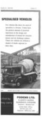 101
101 102
102 103
103 104
104 105
105 106
106 107
107 108
108 109
109 110
110 111
111 112
112 113
113 114
114 115
115 116
116 117
117 118
118 119
119 120
120 121
121 122
122 123
123 124
124 125
125 126
126 127
127 128
128 129
129 130
130 131
131 132
132 133
133 134
134 135
135 136
136 137
137 138
138 139
139 140
140 141
141 142
142 143
143 144
144 145
145 146
146 147
147 148
148 149
149 150
150 151
151 152
152 153
153 154
154 155
155 156
156 157
157 158
158 159
159 160
160 161
161 162
162 163
163 164
164 165
165 166
166 167
167 168
168 169
169 170
170 171
171 172
172 173
173 174
174 175
175 176
176 Pressure Control For Injection Pumps •
Page 128
If you've noticed an error in this article please click here to report it so we can fix it.
ANinjection pump in which the excess-fuel device for starting is controlled by the pressure of the fuel supply is disclosed in patent No. 863.698. The fuel is supplied by a gear-type pump, and the pressure rises with increasing engine speed. (Robert Bosch G.m.b.H., 4 Breitscheidestrasse, Stuttgart, W. Germany.)
The drawing shows the injection pump in section and the fuel-lift pump (I) diagrammatically. The injection unit is of the single-plunger type and distribution is performed by a rotary barrel (2) .driven by the spindle (3). A four-lobed cam (4) reciprocates the plunger.. Excess fuel is provided when spill sleeve (5) is held in its highest-output position by a spring (6). The sleeve is also an hydraulic piston. subject to the pressure of the fuel on its top face, via the duct (7).
In operation, before the engine starts, the piston is at the top, giving the excess fuel setting. As soon as the engine speed rises, so does the lift pump pressure. This forces the sleeve (5) downwards to a position determined by a pin (8).
Pressure created b the lift pump can be adjusted by a spring-loaded reliefvalve (9).
A TYRE FOR SNOW
A TYRE for use on icy roads forms the
subject of patent No. 863,002. Its chief feature is that it can be rapidly converted to or from a conventional form. (Pirelli Societa per Azioni, 94 Viale Abruzzi, Milan, Italy.) A cross-section is shown in the drawing.
The tread has a taper-section circumferential groove in the middle. In this is placed a separate tread ring (1). This is provided with studs (2) which will penetrate ice and ensure a drive. The tread ring also contains inextensible cords (3) which, when the tyre is inflated, force the ring tightly into the groove.
To convert the tyre to suit normal conditions, the ring can be removed by deflation, and replaced by one having a normal tread pattern.
HIGH-DISCHARGE TIPPER
TO enable a tipping body to discharge its load in a high-level heap is the aim of a design shown in .patent No. 863,895. (N. Geertzema, Kolhorn, Netherlands.)
The body, or tip box as it is called, is shown in full lines in the normal travelling position (1). The bottom rear end is linked by a radius arm (2) to the frame, the arm swinging about pivot pins (3). Side-plates (4) attached to the arms fit closely against the outside of the body.
Successive positions of the body as it -n50 is raised by the hydraulic ram (5) are shown in the drawing. The radius arms come against stops when they reach the vertical position, and further ram movement then lifts the body about the pivots (6). Discharge of the contents cannot occur until the body has reached the highest position.
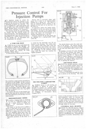
SELF-HEATING CARBURETTER GASKET .rt
A SIMPLE device to aid starting an
engine is shown in patent No. 863,257. It consists of a special gasket for fitting between carburetter and induction pipe, containing a heating element. (G. Cushing, 17 Devonshire Street, London, W.1.) The sketch shown gives the main outline of the device. An electric heating coil (1) is embedded in the gasket earthed at one end and fitted with a lead at the other.
By passing a current of 4 amp. through the coil for two minutes, the region of the carburetter flange is raised to a temperature of at least 89° F. This is sufficient to ensure adequate vaporization of the petrol. As the element is completely buried in the asbestos filling, there is no risk of igniting the mixture.
AIR-COOLED HEAD
PATENT No. 863,485 discloses a design for an air-cooled cylinder head suitable for compression-ignition engines. It is claimed to provide more adequate cooling. (Lanova A.G., 16 Bahnhofstrasse, Zdrich 1, Switzerland.)
A section of the head through the valve axis is shown in the drawing, The chief feature is the provision of what are called heat-conductive walls (1) between the inlet and exhaust passages (2 and 3) and at other points in the cylinder head. In addition to this, the bore containing the injector is, surrounded by several passages through which air an pass.
UNIVERSAL BALL BEARING DATENT No. 865,558 discloses what is
called a universal ball bearing. This consists of one large ball movable in any direction on a number of smaller balls, all held in a cup-ghaped race. (Deutsche Star Kugelhalter G.m.b.H., Schweinfurt, Germany.)