


Patents Completed.
Page 18
If you've noticed an error in this article please click here to report it so we can fix it.
ELECTR MOTOR CONTROL.— Leitner.—No. 23,889, dated 26th October, 1906.—This invention relates to means for propelling road vehicles by shunt, or compound-Wound, electric motors having a controller. It is so arranged that the main circnit is interrupted by an automatic cut out when the motor is running with a weak field. The circuit is reestablished, automatically, an the fields being again strengthened.
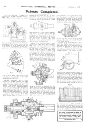
FRONT DRIVING AXLE, — Lamplough—No. 15,861, dated 8th July, 1907. —The driving shaft (a) receives rotary motion from the differential gear (not shown). The driving shaft has a square end (al) which fits in a square hole formed in the boss (f) of the forked member (g). This latter is fitted with ball bearings which surround the ends of the cross shaft (1) of the universal joint. The ends of the other cross shaft (j) are also surrounded by ball bearings, these being fitted within rings (k) formed on arms attached to the wheel axle (1). A semi. cylindrical cover (s), having half hearings (t), fits half the exterior of the casing (p) and lies against the casing (c). When these casings (r, r) are bolted together, they form a complete covering for the casing (p), and also form bearings fur the trunnions (q). The cover (s) is formed with an opening to permit the casing (p) and sleeve containing the road wheel axle (1), to swivel about the trunnion (q) to the required extent.
D RIVING MECHANISM. — Lamplough.—No. 4,485, dated 23rd February, 1907.—This invention provides driving mechanism that will give a positive drive to the front road wheels of motor vehicles, and yet permit of their being steered in the ordinary manner. The road wheel (a) is fixed on a short shaft (b) mounted in a central bearing (e) in the side of cylindrical, oil-tight casings (d, g). Within the hollow trunnions (f) of the inner casing (K) are bearings (dr) in which are mounted the ends of a vertical shaft (1) on which is fixed a worm wheel (j). This worm wheel (j) is driven by a worm (k) mounted on the shaft (1). The worm shaft (1) is driven by gearing from the differential shaft. The vertical shaft (1) has, also, fixed thereon a bevel wheel (m) which gears with a bevel wheel (n) fixed on that end of the road-wheel shaft (b) which is within the oil-tight casing. The outer casing (ii) has fixed thereto an arm (a) which is connected to the steering lever (not shown) whereby the said outer casing (d) can be made to move around the trunnion (f) of the inner casing (g)At the lower end of the vertical shaft (i) is fitted a small pump (p) which forces the oil from the bottom of the oil-tight casing, and delivers it through the pipe (r) on to the gearing.
GUARD FOR MOTORBUSES.—Dennett.—No. 27,670, dated 5th December, 1906.—The guard (f) is pivoted, at c, to the bars or supports (a) carried by the axle (ff). Transverse bars are attached to the guards (f), this forming a suitable catcher. The catcher is main tained in the raised position, shown in dotted lines in Figure 1, by coiled springs (d) placed between the guards (f) and the projections (j) on the standards (1). A buffer (b) is provided, and is composed of a number of flat, parallel springs, pivotally connected at their upper ends to a bar (k) carried by the vertical members (1), these latter being pivoted in turn to the rods (a), at m. The standards 1) are prevented from falling forwards on to the projections (j) by snags, whilst the guard (f) is prevented from being pressed too far forward, by the stop (q).