


Pressure for safe freezer tankers
Page 67
Page 68
If you've noticed an error in this article please click here to report it so we can fix it.
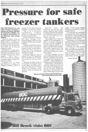
1AW MATERIALS for the ritish Oxygen Company's roducts are cheap, plentiful nd constantly available: it is he output, particularly of ulk deliveries, that creates roblems.
Industrial gases, such as rtrogen oxygen and argon, are btained by air separation. hrough a continuous compresion process the various elelents settle out at different !mperature levels.
Distribution in large quanties as a gas is impracticable, so is is done in liquid form, and in us state they are way down ,etween —196°C and — 83' C. So in order to transport le product safely, special con3iners are needed.
Cryoplant Ltd, of Angle load, Edmonton, London, is a ubsidiary company to BOC. It operates as any other business engaged in producing tankers — that is as a contractor manufacturing cryogenic tankers for customers outside the group as well as BOC.
At the Edmonton complex, Alan SeIly, manager of engineering design, told me a little of the how and the why of tanker building.
Specified standards govern the construction of pressure vessels, he said. Unfortunately, they differ from country to country, but in the UK BS550 and BS1515 apply.
European travel by road is subject to the ADR regulations and yet another set of regulations cover rail and sea transport Although the safety record of the transport of cryogenic liquid is very good, the rules governing the construction of these tankers are constantly under review in order to improve the standard. Stainless steel and aluminium are the two most popular materials used. Copper or copper alloys are also suitable for an engineering point of view, but the cost would be prohibitive, I was told.
Liquid gases boil if they are exposed to the atmosphere. In order to minimise evaporation the tank must be insulated. A method adopted widely is to place one tank within another. The smaller internal tank is the product container while the outer shell contains the insulation material.
The gap between the two skins is exhausted of air and so a vacuum is formed. Extra insulation is gained by the injection of a powder — about 300kg for an average sized articulated tanker.
Alternatively, a multi-layer of reflective aluminium foil and non-conductive fibreglass netting can be used. Experience has shown that although the latter method saves much more weight, a much greater degree of vacuum is required to make it equally effective.
The engineering standards are exacting with either material and require a high standard of welding and cleanliness during construction of the vessels The powder or the composite insulation material must be very dry. Any trace of moisture could increase conductivity.
Perhaps the most critical point in design is the way in which the tanks are supported.
The weight of the inner tank must be transmitted to the vehicle chassis via the outer shell without the low tempera ture following the same path. If the carbon steels used in the chassis and running gear were to be subjected to such extremes in temperature they would become very brittle and fracture very quickly.
The reverse is true for the materials used for the tanks: they become mechanically stronger at cryogenic temperatures. Construction is further complicated in that the supports between the two skins must allow for expansion and contraction owing to temperature changes and to withstand "g" forces during vehicle braking, acceleration and cornering.
Empty running can be the worse load condition, for the container is then subjected to high-frequency shock toads. This can result in failure in high-stress areas at mounting points on the chassis or running gear.
As a general rule at the design stage a safety factor of two is employed. For example, the tank supports for a road tanker are made to withstand a load force of 2g.
Different sets of rules apply to rail and sea containers as these forms of transportation may subject the containers to greater shock loads. There are two basic types of cryogenic road tanker. One, the decant tanker relies on an internal pressure building circuit for rapid discharge of the product. This vessel is designed to withstand about 1,900kN /sqm (275psi).
The second type has a much lower pressure unit of around 300kN/sqm (45psi) and relies on an electrically driven pump for discharge. The shape, wall thickness, stiffeners, baffles and end plates all contribute to the overall weight.
The simplest and strongest tank is cylindrical. The shape and size of the outer vessel is largely dependent on the inner one. Wall thickness is relative to the diameter of the tank. The number of stiffeners required will depend on their individual
strength.
Some materials have a ver high strength to weight rati. and although more expensiv are preferable. To reduce surge baffles are fitted inside the prc duct container, the number re quired being dependent on th tank capacity. Thin deepl dished ends show substantiE advantages in weight reductio, over shallow ends.
The safety record o cryogenic liquids in transit i very good. In the UK, at leasi no serious damage to propert or life has been experience' from tank failure. This is largel attributable to the strict code c manufacture.
It has been estimated the more than 95 per cent of spi lages from all types of tanker are caused by damage to pipe and fittings. Consideration t their location can provide prc tection if contained within th body perimeter.
Operators in this field, as i other types of transport, ar looking towards an increase maximum weight. Most artict. lated tankers now being prc duced at Cryoplant are beini plated for 40 tonne gvw. Nov EEC regulations are hoped ti make them legal for operation e full capacity in 1980_