


An Easily Cleaned Air Filter
Page 36
If you've noticed an error in this article please click here to report it so we can fix it.
IF an air filter be diffic,ult to clean,
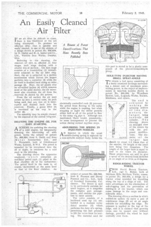
there is less likelihood of the job being attempted, TO produce an effective lter that is quickly and easily cleaned, is. one. of the objects of a design shown in patent No 565,826, by N. Darby and R. A. LiSter and Co., Ltd., Victoria Iron Works, Dursley,
Referring to the drawing, the removal,:of dirt .is. effected , in four stages, each stage dealing with a smaller size of particle, The first stage . .
consists of a constriction (1) immediately adjacentto the air inlet ring. Here, the air is subjected to a sudden acceleration which throws the largest particles into a container (2_) while the air itself is doubled back along an outer passage (3). Next, the air passes over an oil-wetted incline (4) Which removes most of the solid matter; the air movement also circulates the oil from the reservoir ds shown by the arrows.
From the oil Surface the air next passes up into. a:centraI cope, its pa.th being such that, any free: oil is intercepted and drained back into. the reServoir. Finally, a gauze -filter (5) is traversed on the way to the• outlet (6).
The assembly may be simply_ cleaned by the removal of the eentral wing-nut.
DILUTING THE ENGINE OIL Fog EASY. STARTING
ASCHEME for assisting the starting of a cold engine, by teMporarily thinning the lubricating oil'. with petrol, forms the subject of patent No. 565,854, from S. Smith and Sans , (M otor Actessories); Ltd. and T. Waterfield, both of Cticklewood
Works, London, The petrol is intended 'tb be introduced into the oil at night, in readiness for a cold start in the morning.
The drawing shows the apparatus employed; 'which comprises an auxiliarY petrol tank (1) piped to the float chatnber-(2) -of the carburetter. The petrol' level in the tank is, of course, maintained at the same level as that of the &Oat chamber. An electrically controlled cock (3) prevents the petrol from flowing to the suinp while the engine is rurjning, but when stopping at night the driver permits eitherball' Or all of the petrol to flaw to the Sump vik pipe 4: Although not inei;tioned, 'there would, presumably, be some arrangement to prevent the
• action during nortnal daytime stops.
ABOLISHING THE SPRING ,IN INJECTION NOZZLES
A N Injector hi which the usual needle:closing spring is replaced by a non-metallic resilient body, forms the
subject of patent No. 565,796, from E. Paxman and Davey Paxman and Co., Ltd., both of Standard Ironworks, Colchester. The device -is said to be particularly suitable for small engines, as it simplifies the complex port arrangements, and enables the pipeline to enter axially.
The valve consists of a hardened steel tip (1) embedded in a resilient cylindrical member (2) 'which performs the duty of a spring, permitting the fuel pressure to lift the valve from its -seating. The material used for
HOLE-TYPE INJECTOR HAVING SMALL SPRAY-ANGLE
-ro obtain a fuel spray consisting of 1 a finely atomized envelope surrounding a denser care of maximum penetrating power, is the object of improvements in injection -nozzles shOwn in patent No. 565,299,' by Wyndham Hewitt, Ltd., Lagoncla Works, Staines,
Middlesex, and others. . •
• The e n d is achie.ved by snaking the spraying orifices of two diameters, the _larger being towards the cylinder. .1h a drawing . shows an enlarged view of the nozzle tip with the proposed modifications. . The dia.
meter io f the
1.-a. r g,e .r. bore
, should be about 1.2 times that of
the smaller, the length of the small bore being' two diameters. The length of the larger bore is equal to four to six times its diameter. These proportions are said -to give a spray of the desireel,form included in an angle of as little as 5 'degrees.
RIDGE-RIDING TRACTOR WHEEL
FROM David Brown Tractors, Ltd., and C. Riekie, both of Meltham Mills, Meltham, 'Yorks, comes, in patent No. 565,878, a design for a tractor wheel intended for travelling al ng the top of a ridge of soil. The inin advantages are the elimination of soil-clogging and the prevention of sinking-in of the tractor, which can cause damage to the crops and considerable delay.
The drawing snows a section in which welded-on spokes (1) carry a pair of continuous rings (2) set at an angle suitable for straddling the ridge. No pressure is applied to the top of the ridge, and it -is claimed that growing crops can be passed over without damage, provided the, wheel be kept centrally over them.