


Bendix Brake Development
Page 70
If you've noticed an error in this article please click here to report it so we can fix it.
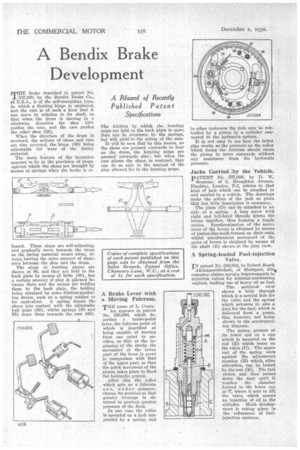
Turbrake described in patent No. 337,268, by the Bendix Brake Co., of U.S.A., is of the self-energizing type, in which a floating hinge is employed, and the cam is of such a kind that it can move in relation to its shaft, se that when the drum is moving in a clockwise direction the shoe (30) pushes the cam, and the cam pushes the other shoe (28).
When the direction of the drum is reversed, the actions of shoes and cam are also reversed, the hinge (50) being adjustable for wear of the facing material.
The main feature of the invention appears to lie in the provision of stops, against which the shoes are brought by means of springs when the brake is re leased. These stops are self-adjusting, and gradually move towards the drum as the facing material wears away, always leaving the same amount of clearance between the shoe and the drum.
The stops or locating pieces are shown at 86, and they are held to the back plate by means of bolts (88), but a certain amount of play is allowed between them and the means for holding them to the back plate, the holding being obtained by some friction-producing device, such as a spring washer or its equivalent. A spring draws the shoes into contact with the adjustable hall joint (50), 'whilst springs (80 and 78) draw them towards the cam (66). The friction by which the locating stops are held to the back plate is more than can be overcome by the springs, but will yield to the action of the cam.
It will be seen that by this means, as the shoes are pressed outwards to bear on the drum, the locating stops are pressed outwards also ; but when the cam allows the shoes to contract, they can do so only to the amount of the play allowed for in the locating stops.
A Brake Lever with a Moving Fulcrum.
THE name of L. Coata
len appears in patent No. 336,696, which describes a brake-pedal lever, the fulcrum point of which is described as being capable of moving from one point to another, so that at the beginning of the stroke the movement of the lower part of the lever is great in comparison with that of the upper part, so that the quick movement of the piston takes place to flood the hydraulic system.
After this the roller which acts as a fulcrum can, un der pressure, change its position so that greater leverage is obtained to produce greater pressure of the fluid.
In one case the roller is mounted on a fork suspended by a spring, and
in other instances the fork may be controlled by a piston in a cylinder connected to the hydraulic -system.
It is not easy to see how the latter plan works, as the pressure on the roller which forms the fulcrum should cause the piston to move outwards without any assistance from the hydraulic pressure.
Jacks Carried by the Vehicle.
PATENT No. 337,008, by D. W.
Sessions, of 3, Broughton Avenue, Pinehley, London, N.3, relates to that kind of jack which can be attached to and carried by a vehicle. The drawings make the action of the jack so plain that but little description is necessary.
The plate (D) can be attached to an axle or a spring. A long screw with right and left-hand threads draws the levers together, thus forming a toggle action. Synchronization of the movement of the levers is obtained by means of pinion-like teeth formed on their ends, whilst simultaneous movement of the pairs of levers is obtained by means of the shaft (B) shown in the plan view.
A Spring-loaded Fuel-injection
IN patent No. 336,582, by Robert Bosch Aktiengesellschaft, of Stuttgart, this, company claims certain improvements in ' injection valves for internal-combustion engines, making use of heavy oil as fuel.
The sectional view shows a body through which is a central hole for the valve and the spring which actuates it, also a duet for the fuel, which is delivered from a pump, this, however, not being shown in the accompanying diagram.
The spring presses at its lower end on a cap which is mounted on the rod (E) which bears on the valve (0). The upper end of the spring rests against the adjustment member (H) which, after alteration, can be locked by the nut (M). The fuel enters and then passes down the duct until it reaches the chamber formed in the lower cap at T, where it acts to lift the valve, which causes an injection of oil in the cylinder. . Much development is taking place in the refinement of fuelinjection systems.