


TYPES OF TIPPING GEARS.
Page 12
Page 13
Page 14
Page 15
Page 16
If you've noticed an error in this article please click here to report it so we can fix it.
The Mechanism for a Useful Form of Municipal Vehicle Classified and Technically Described.
MANUF.A.CTURERS of motor vehicles have realized that the ordinary fixed type of lorry body is not entirely suitable for certain classes of work, particularly such classes as are required in municipal work and in building construction.
The efficient handling of refuse, road repairing material, sand, etc., requires that bodies sheuld be capable of tipping in either ,an endways or a Sideways direction, so that the contents of the body slide out and do not require the considerable amount of manual labour which would otherwise be necessary.
Many forms of gear are already in existence, and new ones or improvements on old types are being rapidly produced. Some of these designs, however, appear to be unduly complicated, whilst others, which are intended to be operated by hand, appear to require an excessive amount of labour.
The variOus types of end tipping gears can be placed under the following classifications:—
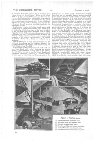
(I) The simple single or twin screw, pivoted at its base and operated either by hand.or by.power. It is sometimes geared down and may be arranged to give a quicksreturn of the body-to the horizontaposition. (2) The differential -screw. This consistsy of one screw operating within the other, so that when the inner screw reaches the limit of its travel the,' outer screw begins to turn. This type can beniacleto'give either urnfOrm speed of lift or two different speeds.
(3) The horizontal simple single or twin screws, with either plain or toggle-jointed levers. In this type, the body usually runs back some distance until the load practreallY balances over the,pivotingtpoint.
(4) The horizontal simple screw with a:plam)push rod attached to its nut. The .body in this type is fitted with, rollers and runs back on speciallyshaped guides, attached to each side member of the frame.
(5) Single or double hydraulic rams,pivotecliin front of, the rear,axle*and:practicilly•in the vertical Plane. (6) A hydraulic ram acting in a, virtually ..vertical plane; but situatedrbetween the cab and the body, and lifting the body through the medium of pulleys situated,at the top of the.ram which carry.wire repes attached.at one side to the frame and at the other to the body.
(7) The horizontal hydraulic ram, by which two levers pivoted at their bases, are pulled into an upright levers, against two rollers fixed to the bottom of the body. As the levers lift, the rollers rim up them and, so lift thebody.
(8) The runway type in. which specially shaped channel girders are fitted to the chassis. lathe channels of these girders run pulleys fixed to the bottom of the body. Such bodies can be tippedhy means of a simple screw and lever or by an endless 'chain' which canpull the body in either direction and. which raa,pbe hand:or power operated.
(9) The winch type, in whiCh the winch is band or power-operated, and the rope.aCts.-direct on. the body or through the medium of levers.
The number of side tipping gears is comparatively small and, on wagons, is usually confined to those bodies which are constructed with separate tipping' compartments. In most cases; the operation of these is by siMple screws placed across a frame of the vehicle, theebody being tippecbby plain or'toggle levers. In some Cases, where.either-s0e tipping. is-. required, the screws and levers are duplicated, one set being utilizedjor one side and the other set for the other side. Side tipping of the whole body is usually Confined to trailers, the method of operation being very sithilar to that used on side tipping bodies fitted to CA • 378 lorries, except in the case of one example in which a single hand-driven shaft at one side of the frame operates, by means of two sets of bevel gears, simple screws situated at each end of the trailer. This type we will describe more fully later in'the article. In addition to these gears, there are a few unloading devices ,which, although not exactly tipping gears, perform similar funetion.s as regards the unloading of the material, amongst these are the Craymer un loader and the. Wilkin sainkrader. A few of the side tipping gears fitted to lorries also utilize some form of runways in which run pulleys fixed to the bottoni of the body. The body can then be pulled to either side by means of plain screws and levers or by chain gear.
Methods of Power Operating.
As regards those tipping gears which are operated mechanically, there is considerable, variety in the methods used. On petrol vehicles, the drive is often taken from the gearbox, but, unless provision has been made for this in the original design, considerable difficulty may be 'experienced in adapting this farm of drive.
In one or two designs, the power is obtained from sprocket wheels fitted between the front of the gearbox and the clutch. In one make, a sprocket is actually fitted to the eardan joint in front of the
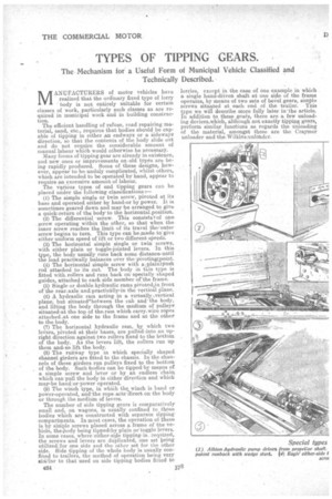
gearbox. On the Albion hydraulic tipping wagon, the pump is mounted under the driver's seat, and the drive is taken from the propeller shaft by means of a roller chain. In the case of electrically-propelled vehicles, the matter is considerably simplified, as a separate motor can be installed. This motor is usually of 1 h.p. On. steam driven vehicles, the drive is usually taken direct from the engine either by a throw-in gear or, as in the case of the Garrett, by a belt from the crankshaft.In the Foden wagon, the hydraulic tipping gear is operated by pressure obtained fromathe boiler feed, pump, a very simple method which utilizes existing parts and thus tends to avoid over-complication.
It must be. remembered that, in the case of those tipping gears which utilize practically direct lift, the situation of the gear may have considerable influence on the power required. If the type used is a. hydraulic ram situated just in front of the rear axle, the lifting power will have to be considerable, because the weight of the body and its load not only rests on the ram to a great extent, but also exerts considerable leverage upon it. Even with a screw gear situated at the forward end of the body, the load to be lifted will often amount to quite half the total weight of the body and its load.
-Wherever the power be obtained from, it is essential tha.O.it should be automatically shht off when the body, reaches the end of its travel in either direction. Not only is this necessary, but means must be taken to maintain the body in its fully-tipped position, or, itnecessary,'at.any positiOn between its normal position and its fully-tipped position, and also to prevent the body from returning to its normal position too 'rapidly. Preferably, the driver shoUld be able to control the tipping, gear from his seat, though an even better arrangement would be to arrange the operating mechanism so that it can be controlled either from the driver's seat or from the side of the vehicle.
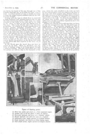
Dealing with the various forms of tipping gear in the order .into which we have classified them :— The simple screw. type, when hand-operated, is suitable for-work where plenty of labour is available. It is not satiSfactory,where labour is limited. To lift a full load may require as much as 50,000 ft. lb. f work and, though most of the makers will assert that a loaded bOdy can be tipped in two minutes, this work is; rather too much to require in the time for one man, as a man can. only do work at the thaxiMum rate of one-third horse-power, and that for .short periods only. That is to say, his maximum outPut would be 10,000 ft. lb. per minute. To obtain the necessary tipping height, the screws have usually to be unduly long. A very interesting type of simple screw gear is that fitted to the new two-ton Edison. In this type toggle levers are used. Ole nut has a long tubular extension whi&hfalidee over the screw, and the cross arms of the toggles are pivoted to:-this nut. The result is that the body is raised considerably more than the distance the nut travels on the screw. The use of a long screw is thus. avoided. In this particular instance, the tipping gear is electrically operated by a separate motor, and the time taken -to tip a fully loaded wagon is between 15 and 20 seconds. Incidentally, on this wagon, the pivots for the body are situated not far from ,the centre,' and thus the work to be done by the tipping gear is not great. On the Mann steamer, the simple screw is replaced by a steel pin-rack, which is raised or lowered by a pinion operated,through worth gearing.
The differential screw. The remarks which we applied in connection with the simple screw type also apply in this case, except that the screws do not have to be so long, and, therefore, less whipping occurs when. the body is in its normal position. Numerous examples of this type are now being fitted to vehicles and, when power driven, they seem to give satisfaction. A well-designed gear of this type is fitted to the Pagefield tipping wagon. This
379 e25
is 'operated from the gearbox by a throw-hi gear which drives two bevel wheels. These bevel wheels float on a cross shaft of the gear, and between the two is a double dog clutch, which slides on a squared portion of the cross shaft. By sliding this dog clutch into engagement with one or other of the two bevel wheels, the cross shaft is turned one way or the' other, and through a second set of bevels, rotates the differential screws.
Dealing now with the horizontal simple screw, with either plain or toggle-jointed levers, this seems to be an eminently satisfactory type, as the work required to run the body back until it balances over its pivoting point is very little, as is also the amount required for tipping the body, owing, to the load being on the balance. There seems however, to be room in many examples of this type for simplification. The number of rollers, slides, etc., should be reduced to a minimum.
Typical examples of this Successful type are the patented tipping gear on the Yorkshire steamer, the Constable patent tipping gear, and that made by the Eagle Engineering Co., Ltd.
With regard to the horizontal screw with push rod and body fitted with rollers running on shaped guides, a good example of this type is the Edison, one of which was shown at the recent Roads and. Transport Exhibition, fitted to a, Lansden vehicle. In this type, a connecting rod from the nut to the body pushes the latter along. Rollers fitted to the body rest on two specially shaped guides attached to the frame members, and the body, as it runs back, is constrained to move in a path which follows the contour of the guides. On the Lansden, the screw is operated through the medium of a chain by a small. electric motor. This method seems to be quite satisfactory, and its application is certainly very simple.
Examples of the single or double hydraulic rams pivoted in front of the rear axle are to be found on. many vehicles. A particular make which is used on several is the Bromilow and Edwards twin ram. Rams of this description are usually supported by a very strong cross-member in which they must, of course' swivel. An objection to certain of this type is that the bottom of the barrel is sometimes brought too close to the ground, the clearance being as little as 6 ins., but there appears to be no reason why this clearance should not be increased. Certainly, the rams operate very freely. and the body can be lowered very gently by allowing the oil to escape slowly. At the end of the travel of the plunger there is usually a release valve or port, so that, even if the pump continues to operate, the plunger will not be forced to a greater height than is necessary. As has previously been mentioned, this type of ram has to withstand ,considerable loads, and must, consequently, be of very stout constructibn. The Medium which is used in the ram is usually alight lubricating
oil, fed to the barrel of the ram through one of the trunnion bearings, but, on' atleast one type, water is used.. A certain aniount of care is usually necessary to keep the pump in good condition and all the connections oil-tight.
Dealing with the type in which there is employed a single hydraulic ram, situated between the cab and the bodyand having pulleys which carry wire ropes attached. to the frame at one side and to the body at the other, we know of only one tipping gear of this type. This is the Woods, and is an American production. It is fitted by several manufacturers of English vehicles, including Leylands, Ltd., and Caledon Motors, Ltd. Owing to its pOsition, it does not have to bear the same strains as does the ram in front of the back axle and, as ample room can usually be left between the cab and the body,,its,dimensions are not restricted by considerations such as ground clearance and limited space between the body and the chassis. The smaller rain or rams, as usually fitted in front of the axle, have to exert approximately double the pressure, as the lift at that point is only about half that required at the front end of the body: In the Woods gear the barrel does not have to swivel on its base. There is , therefore, less liability of leakage owing to oil. being passed through a trunnion bearing. The wire ropes which pass over the pulleys are held by clips to the baseplate of the
ram, whilst the ends attached to the body are held. by two long brackets which are bolted to the front of the body and which project some distance below it. Oil under pressure is delivered either above or below the plunger according to whether it is required to raise or lower the body. To allow for any leakage of oil which may possibiy occur, the barrel contains rather more oil than is actifally required to move the plunger to its full height. Dealing now with the horizontal ram type, we know of only one manufacturer who fits this novel type of tipping gear. The particular example we have in mind is known as the Horizontal iHydraulic, and is an American production, which is being fitted to Daimler vehicles. Incidentally, MI Daimler Co. have an agency for this make cif gear. The ram is situated along the centre line of the chassis just in front of, but, of course, above,'the rear axle. The plunger is projected towards the rear of the vehicle. At. its head it carries a cross piece, which pulls two links connected to two levers pivoted at their bases. When the body is in its normal position, these levers lie almost flat. As they are forced up, rollers' on the bottom and at about the centre of the body 'run up against the rear faces and consequently force the body to lift, The pump used with this gear an forming a unit with it is of the eccentric type and, on the Daimler vehicle, is worked by a short canlan shaft driven by gears fitted to the top of the gearbox. This particular gear gives a very rapid lift and has actually tipped two tons of granite in seven seconds. The tension on the links, however, would appear to be tremendous, as the leverage exerted on them by the lifting levers is considerable.
To deal with the runway type, in which specially shaped channel girders ase fitted to the chassis and control the movements of the body, few, if' any, of this type of tipping gear are in -use in this' country, but a very simple and effective one is made in several forms by E. Fouchee, 227, Boulevard Peseive, Paris. In this type, two channel side members are situated. immediately over the ordinary side members of ,the chassis, being extended back and in adownward direction at the rear of the chassis. The body is supported by rollers which run in the channels of these pressed steel niembers,, and the body is moved along these members by means of a continuous wire rope. When the rear rollers reach the inclined portions of the channels they tend to run down them, and to lift the front rollers out =of the channels and, in order to allow this to be done, the top wens are cat away for a short distance, so that these front rollers and the front end of the body can lift. This method would appear to be a very cheap and satin factory way of dealing with the difficulty. It re
quires very little force to run the body back to the point where the rest of the operation is practically performed by its own weight and that of the load.
Regarding the winch type., one or two interesting examples are employed.
Electromobiles (Leeds), Ltd., on one of their models use a winch which is positioned in the cab behind the driver's seat. The winch is driven by a small electric motor through the medium of a doublereduction gear consisting of a worm and wheel and two spur gears. The wire rope from the winch passes over a pulley at the top of and at the back of the cab. The cab, in order to take the strain, is suitably strengthened by a framework built of angle iron and fitted'with tie rods. The rope passes over the pulley and thence round a floating pulley which is attached, by means of two short lengths of chain, to extension = brackets at the front of the body. The rope is then carried back and its end fastened close to the pulley on the cab. The body, in this ease, is lifted direct and is pivoted at the rear.
An interesting winch-tipping gear is fitted to a refuse-collecting vehicle in the employment of the Paris municipal authorities. In this gear, two sheer legs are fitted to the bottom front end of the body, which is pivoted at the rear. The ChaSsis carries channelled runners at each side which carve up towards the cab. Wheels on the ends of the sheer legs run in the channels. When theloody is in its normal position, the legs fold back and lie in a; horizontal position. Wire ropes from the winch pass over the pulleys fixed to the oab and are attached to-the ends of the sheer legs, and when these ropes are wound the sheer legs travel along the runners and
c28 the body is consequently lifted and can be tipped to an angle of 45 degrees. When the body is down, the ropes lie along grooves in the sheer legs, and at first the lift on the body is direct until the legs attain the position at which they can lift the body themselves. The top portions of the legs then leave the ropes
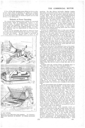
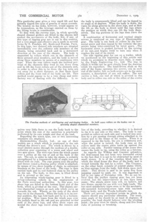
A combination of horizontal and vertical simple screws is employed on one type of Electromobile gear. The body is run back on rollers by the horizontal screw and then tipped by the vertical,' the two screws being inter-connected-by bevel gears. .„ The horizontal screw is pushed forward by the turning of its nut and begins itself to turn only when it reaches the end. of its travel. The side tipping -gear for use on a trailer, Which. we mentioned at the beginning of this article and which we promised to describe more fully, is made by the Eagle Engineering Co., Ltd. The way in which it works can he seen clearly fromthe drawing 'which we reproduce. The hand-driven shaft at the :side of the frame operates two screws, one at each end df the trailer, hut, as both screws act in the same manner, a description of one will suffice. The nut carries a link, one end of which is pivoted to the body and to either one side or the other of the centre
line of the body, according to whether it is desired to tip it to cue side or the other. The body is supported on rollers' at each side and is locked into position by a pin passing through plates attached to its centre and to the frame of the trailer. When it is required to tip the body, the pin is withdrawn and, when the screw is turned, the body runs on the rollers until the centre plate butts up against the roller at one side. Further turning of the screw then causes the body to tip, using the roller as a fulcrum. As regards the Wilkins and Craymer pnloaders, the first-named has not been very successful owing to the fact that it is apt to be obstructed by sand or small stones. It is of the venetian blind type, in which the blind forms the floor of the body, and is wound towards the end. by a'roller. The Cramer, on the 'other hand, consists of jointed plates which, as they emerge from the body, fold down upon each other. This device is said to he quite free from janisaing _caused by sand,. etc. It was described in full in our issue of, November 18th. e
We do not be
that the perfect tipping gear has yet been evolved. butthe improvements of late have been many'. The simple screw type will, we believe, fall into disuse, except for use with very light loads. The two most satisfactory types seem to be the mechanically-operated horizontal-screw type with run-back tipping body, and the Woods hydraulic rain. There are several important points to which designers should pay particular attention. The maximum angle of tip should be at least 45 -degrees; if possible, the load should balance over the pivoting point;, the gear must he simple, cheap and free from risks of jamming or breaking.