


Rolls-Royce Powered Steering
Page 72
If you've noticed an error in this article please click here to report it so we can fix it.
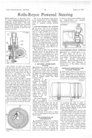
71-1E application of hydraulic assist' ance to a steering system is shown in patent No. 777,866 (Rolls-Royce, Ltd., Nightingale Road, Derby). The chief feature is the mechanism used to operate the hydraulic control valve; this, as is shown in the drawing, is built into the steering-worm box.
The column (1) does not direct y work the worm (2) but it moves via an internal-external pair of spur gears (3). Passing through the hollow centre of the worm is a rocking. lever (4); this is centred by, and pinned to, a semispherical member (5) housed in the bottom of the column assembly.
The lever passes through a second semi-spherical member (6) centred in the worm unit and, owing to the offset of the two axes, the lever rocks one way or the other when the column is turning. The rocking movementis permitted by tangential yielding of the internal -gear because it is supported only by a remote bearing, whereas the external gear is rigidly Positioned by the worm bearings.
The ball-end (7) engages with a slot in a slide valve (shown end-on at 8) and moves it to control the hydraulic fluid.
The servo cylinder is connected to a second bell-crank on the opposite side to the one directly moved by the droparm. One of the advantages of the system is the compactness of the installation, which would obviate major modifications in adapting existing steering gears.
A NON-REVERSIBLE OIL ENGINE I F the power unit of an oil-enginc,d vehicle be turned backwards accidentally, it is quite possible for it to start and run. This is a serious matter, as the engine is then completely out of control because the governor mechanism moves to the full-throttle Position. Moreover, reversal of the oiling system can rapidly cause a seizure. A one-way drive for the injection pump, to render reversal impossible, forms the subject of patent No. 776,387. (W. Appleby, G. Whitehead and The Austin Motor Co., Ltd., Birmingham.) The clutch is built into the driving sprocket carried by the spindle of the injection pump. It consists of two concentric parts, interconnected by a pawl (1) which is pressed into contact by a spring-loaded plunger (2). The outer member has only one recess to receive the pawl, so that the timing is not lost if relative rotation occurs.
A RICARDO COMBUSTION SYSTEM
PATENT No. 777,970 shows a combustion chamber for oil engines which is said to have good combustion characteristics and is not too critical in respect of manufacturing tolerances. (Ricardo and Co., Engineers (1927), Ltd., 21 Suffolk Street, Pall Mall, London, S.W.I .)
Referring to the drawing, the chamber, which is located entirely in the cylinder head, is barrel-shaped, having a flat at top and bottom. The lower half (1) is made as a "hot plug" having limited heat transfer ability to the surrounding walls.
The connecting passage (2) is approximately rectangular in cross-section and breaks into .the fiat bottom of the plug. Were the chamber spherical, the location of the passage would be critical, but the use of a flat surface permits tolerance both in the position and the angle.
The direction of air swirl is about an axis at right-angles to the axis of the barrel shape.
THE HARDENING OF CRANKSHAFTS
AHARDNESS pattern for crankshaft bearings is shown in patent No. 778,504. The hardness extends from the cylindrical portion around the
radius in the corner.. But only one corner of each bearing is so treated; the other is left soft so that truing-up can be done by deformation without cracking. (Daimler-Benz A.G.. StuttgartUnterttirkheim, Germany.) GAS-TURBINED ROAD VEHICLES
PATENT No. 778,502. shows a free piston engine for use as a gas generator for driving the turbine of a road vehicle. The patent deals mainly with the starting arrangements employed. (Societe d'Etudes et de Participations Eau, Gaz, Eleetricite et Energie S.A., 12 Rue Diday, Geneva, Switzerland.) RESILIENT MOUNTING FOR TANKER VEHICLES I ONG tanks, such as those used for
the bulk transport of milk and other liquids, should not be subjected to strains arising from chassis distortion, and patent No. 777,434 shows a method of mounting the tank in order to achieve this. (Mickleover. Transport, Ltd., I. Taylor and A. Turner, all of Twyford Works, Whitby Avenue, Park Royal, London, N.W.10.)
Differing methods are used at the front and the back of the tank; the front mountings consist of brackets (I) each containing a conical-rubber bush .separating two metal cones. This arrangement gives a measure of vertical freedom but otherwise the position is fixed.
The rear mounting employs a construction rather like a spring shackle, as shown at 2. This, whilst firmly holding the tank, permits a slight sideways freedom and a small amount of rotary. motion.