


A High-efficiency Non-servo Brake
Page 46
If you've noticed an error in this article please click here to report it so we can fix it.
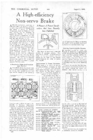
A Resume of Patent Specifications that have Recently been Published ABRAKE mechanism employing no servo effect, yet giving a mechanical advantage of 30 to 1 between pedal and shoes, is shown by Bowden (Engineers), Ltd., of Willesden, London, N.W.10, and R. Tondeur, in
patent No. 430,442. In this design rolling friction is substituted for rubbing friction, and it is to this factor that the high efficiency is due.
Several shoes are used in one drum, four or more being preferred in order
to eliminate drum distortion. Each shoe swings on a pivot (2) and has, on the underside, an inclined serrated surface (3) -upon which a similarly serrated roller (5) operates, the roller being pressed on its other side by a freely rotatable serrated ring (1). Rotation of this ring in a clockwise direction moves the roller up the inclined track and presses the shoe into operation. The ring (1) is manually operated by a pinion (4), around the spindle of which is wound a pedaloperated nowden cable.
A Pre-selective Eight-speed Constantmesh Gearbox.
AGEARBOX of the dog-clutch type, containing only four pairs of gears, yet giving eight speeds forward, and four reverse Speeds, if the necessary
idlers be used, is shown in patent No. 430,699, by Maybach Motorenbau G.m.b.H., of Friedrichshafen, Germany.
The chief feature of the scheme is the method of shifting the dogs, by which the engagement of one set of dogs results in the simultaneous meshing of a second pair. This is achieved by the use of centrally pivoted arms (2 and 3) which move an upper and a lower dog at the same moment. The operating levers are moved via the medium of springs (1) in the control rods ; this makes the gear pre-selective, as the dogs, being undercut, will not release under load. Furthermore, owing to the angular end-faces of their teeth, engagement will not occur until the speeds approximately synchronize.
B40 The shape of these teeth forms the subject of previous patents, Nos. 298,186 and 347,570. A special form of tooth, by the same concern, was described in the issue of this journal dated February 23, 1934, in patent No. 404,567.
Improvements in Torque Converters. THE name J. M. Voith, of Heiden' deim-am-Brenz, Germany, is well known in connection with hydraulic gears of the Fottinger type, and patent No. 430,410 by the above concern deals with a modification intended to prevent a loss of efficiency.
• The patentee states that in this type of gear, the escape of liquid between the elements often results in a serious loss of efficiency, not so much from the actual escape but owing to the liquid expending its kinetic energy on some other part of the mechanism moving at a different speed.
The drawing shows a section of a gear in which the revolving casing (2). throws out liquid via' the aperture (3). Instead of being disregarded, this escaping fluid is led into a catchment ring (1) which leads it back to the initial ports. The type of gear shown is stated to be particularly suitable for vehicle use, and is put in and out of operation by filling or draining the casing, which operation can be performed at will and minimizes drag, Relieving Injector-pipe-line Pressure.
pi injection systems in which the 1 nozzle is closed by a spring-loaded needle, the pipe-line from the pump is kept under high pressure between injection periods. According to Simms Motor Units, Ltd., Gresse Street, London, W.1, and R. L'Orange, this feature is undesirable owing to the nozzle being at all times very near to the dribbling
point. .
A means for relieving the line pressure between injections is described by the above concern in patent No. 430,663. The device consists of a
double valve inserted in the head of the pump cylinder. In the drawing, a spherically seated valve (1) is held on to its seating by a spring which also closes an oppositely directed poppet valve (2). In operation, oil is forced past the valve (1), and, after injection has terminated, the central valve opens sufficiently to relieve the pipe-line pressure to below the dribbling value. The washer (3) is interposed to prevent a broken valve from dropping into the working space of the pump.
It is obvious that the valve (2) cannot open open until the pressure on the pump side of it has fallen below that in the pipe line. Other modifications are described in
an additional patent, No. 430,579.