


HINTS ON MAINTENANCE.
Page 66
If you've noticed an error in this article please click here to report it so we can fix it.
Packing Spring Pads to Allow for Road Camber. Experiences with Tylor Engine Lubrication. Silencing Foden Gearing. A Ford Coil on a Trojan.
Obviating the Effect of Road Camber.
IT is found that the camber of the average road tends to throw more weight on the near side of a wagon than the off side, with the result of weakening the near-side spring and causing the body of the vehicle to tilt. Some makers of heavy vehicles have overcome this difficulty by fitting a stronger spring on the near side. Drivers, on the other hand, when loading their vehicles with goods which can be "packed," arrange so far as possible to give the off side more to carry than the near side and thus the ill-effects of a steeply cambered road are more or less overcome.
Quite a number of vehicles, however, Is fitted with springs of equal strength, and the majority of loads cannot be "packed." It is therefore necessary that something be done to counteract the action which a cambered road produces, for if one side be down more than the other still more weight is automatically thrown on to this side, and very often a breakdown will result unless preventive steps be taken. The most satisfactory method is to have a stronger spring on the near side, but if for any reason a stronger spring is
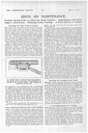
not available, a very satisfactory way of overcoming the difficulty. is to pack up the spring on the near side by putting suitable steel pads between the spring ends and the spring slippers. If reference be made to the accompanying sketch, it will be seen that on some makes it is not possible to put the pads (A) between the spring ends (B) and the slippers (C), for if this be done the spring would be thrown too low to allow the slipper pin (D) to pass through the slot hole in the slipper, and when this is the ease it is necessary to place the pads between the slipper and the channel iron (E).
The only parts required for this alteration are two pads about 1 in. thick and four long bolts (F).
Some Experiences with the Tylor J.B.4. Engine.
ONE of our readers wtho has had a great deal to do with the running of the 3'.B.4 Tylor engines formerly fitted to A.E.C. lorries tells us that two coaches fitted with these engines have required no bearing attention whatever in tl.ree years. One lorry had a big-end bearing run very slightly after 18 months, and a second lorry, which is used on a milk-collecting round seven days per week, summer and winter, for three years, ran its first big-end bearing after that period. It is extraordinary to learn that this particular vehicle averaged 95 miles per day for many months and 50 per day for the others, the average mileage per annum being over c44 26,900. In fact, the total for the three years was close on 80,000.
Some time ago it was suggested that to avoid trouble with the pressure-relief valve this should be removed altogether and a screwed plug fastened in its place. Two days after carrying Out this operation the intense pressure, when the oil was told, burst the dashboard oil gauge; next, the big-end referred to ran out and a small brass plug screwed Fin, gas was found in the sump. This was discovered to have blown out of the crankcase, where it is fitted behind the intermediate timing wheel, closing the end of the oil duct by means of which oil is fed to the timing gears and to the pressure gauge. The oil pressure had caused the threads in the -aluminium to strip and, of course, the No. 4 big-end was then starved.
On the other hand, a relief valve was a constant source of worry and loss of running time because fragments of carbon or other foreign matter got under the ball and reduced the oil pressure from 30 lb. per sq. in. to 5 lb. per sq. in.
The solution of the difficulty was found by removing the relief valve, fitting tightly screwed plugs into the i-in. holes in the cover and drilling two holes it in. diameter in the relief-valve body at such an angle that when the valve was screwed into place in the oil-pump easing any oil which passed the ball when it was lifted from its seat was directed to the revolving crankshaft. These holes prevented either the pressure gauge bursting or the screwed plug from blowing out, but they would not allow sufficient oil to pass through the relief valve, if this was ever held open, as this would seriously interfere with the normal pressure in the bearings.
In one case a cage made of coarse-mesh copper gauze was soldered into position to enclose the bottoln of the oil pump, but, so soon as the gauge became partly clogged up, the increased suction drew it into the pump gears, which stripped the skew gears of the drive and resulted in all the big-end bearings running out.
Silencing the Gearing on the Foden.
WHEN a steam wagon is turned out from the Foden works the gearwleels are silenced by fitting segments of wood into the side of the gears. These pieces of wood in time become worn, oily, and finally are often lost, in which case new pieces 12 ins. by 3 ins, by f) in. should be drilled and bolted in position.
Noise is often caused by the driving pinion being too deeply in mesh as the result of the crankshaft brasses becoming worn. To test for this trouble entails the use of red raddle, which, when rubbed on the teeth of the pinion, will show if the mesh be too deep. The correct clearance between the pinion and gearwheel with the boiler steam pressure at 200 lb. per sq. in. is A02 in., .and if less than this, it is necessary to place a piece of metal packing (such as sheet tin) between the crankshaft brasses and their housing.
A Coil Replacement on a Trojan.
THE induction coil of a Trojan van recently developed a fault which caused the engine to fire very unevenly. The van was urgently required for work and a new coil of thesame type was not then available, so a Ford
coil was used to replace the faulty one. ' To allow this to be done, three wireless terminals of .the screw type were soldered to the three contact points of the coil, the battery-to-coil wire was then connected to the terminal base, and the coil-to-timer wire to the upper of the two side terminals. The high-tension wire from the coil to the distributor was fastened to the lower of the two side terminals. Packing was placed round the coil to prevent it jolting about.