


AN INTERESTING CHANGE-SPEED GEAR.
Page 34
If you've noticed an error in this article please click here to report it so we can fix it.
A Résumé of Recently Published Patents.
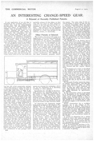
A new application of an old idea is embodied in the invention which is destribed this week by Zahuradfabrik Geschellschaft Mit BeschrankteaHaltung and others, he specification No. 158,085; that of providing means, in a gearbox, whereby thegears can be changed automatically upon release of the dutch, the preparation for the change having been made some time previously by the shifting of the changespeed levers. A well-known example of the kind of box which we have in mind is the Liuley, which is employed on some Commer Cars. Others of the same type will, no doubt, occur to our readers.
In the specifiation under review a box, providing four speeds and a reverse, is described and illustrated. There is one striking rod for each change of gear, and these five striking .rode stretch the full length of the box, protruding at each end. There are collars at both ends of every rod, and intervening between those collars at the rear ends and
the box are coiled compression springs; which tend always to press the rods in a rearward direction, which is that in Which they must move in -order toengage their respective gears. The eluteh pedal is also mounted within the box, on a spindle at the bottom of the box. There is a crossbar mounted inside the box., in such a manner that it lies just beneath the Ave change-speed sods. affis cross shaft or bar moves to and fro with the clutch pedal. In forward .motion (when the clutch is being withdrawn) it comes into -contact with stops on the five rods, and draws them ail forward.disengaging any gears which may be in mesh. The arrangement is-such that the clutch is first Withdrawn; further movement of the pedal then disengaging the gears. With the rods in the forward position, plungers fall into place in notches in the rods and prevent movement backwards when the pedal is yeleased and the clutch engaged, except in the case-of that gear which it is required to engage; for that' one the plunger is held out, and the sod concerned slides right back; following the clutch pedal, and engaging the correct gear before the clutch itself is actually engaged_ The plunger may be manipulated some time before thechange of gear ie., required, and withdrawal of any plunger auto
B38
Other Patents of Interest.
rnatically releases all the others, so that they fall into place in their respective notches in the rode' and prevent the engag-ement of more than one gear at a time. The plungers may be operated mechanically by means of press buttons disposed in a little case secured to the steering column,or electrically.
We recently referred on this page to a -tipping gearwhich had been patented by Tilling-Stevens Motors, Ltd.; whereby the, power of the electric transmission Was used direct .fcir the purpose ef tipping the .wagen. " A short -shaft was disposed between the rear end of the engine or _Muter shaft arid the propeller shaft,and a sliding wheel on this shaft engaged either with the 'propeller shaft. or with the other by which the power was transferred to the tipping gear. In another specification, No. 165,196, by the same inventors, precisely similar
means are adopted for arranging a drive for all the machinery , of a travelling workshop or ether purpose. •
Specification No. 141,380,by the Cleveland Tractor Co., describes several improVereents -to the detail construction of the tracks of their well-known chaintrack tractor. 'They are in the main, directed towards protecting the mechanism of the -track from being fouled by dirt and Mud, which is inevitably picked up by the tracks as they traverse a field.
An ingenious and apparently simple form of gas producer is the subject of No. 164,767, by J. W. Bradbeer Stokes and another. The two principal.components, the producer and the scrubber or. purifier, are disposed.one on each side of tbe" Wagon, close to the front wings, so that the appearance of the lorry is kept more or less symmetrical. The producer is, Cs it were, in four tiers. The lower one is the ashtray. Above that comes the furnace proper, then a water-jacketed portion, and, finally, the. fuel hopper. The floor of the ashpan is conical, so that the opening of sliding doors in the wall allows the ashei to drop oat. The fireliare are designed to reVolve, either at
of the driver (Who, presumably, gives a, pedal or hand lever an occaskeet push) or by mechanism driven by. the engine. outer edge of this re volving firebar is spiral, so that the fire is agitated thoroughly when the bars are revolved. The furnace is firebricklined, while the water for the jacket of the next tier is kept at its proper level by means of the familiar float charnber. As the water in the jacket evaporates, the istearn formed is drawn into the fire along with the air supple*, means being provided whereby the driver may legislate the proportions of steam and air. The scrubber is a dry one, and is stated • to be self-cleaning.
No. 164,501, by F. H. Dutton, has to . do with it-acter-cum-frailer combination vehicles of the six-wheeled type. The fore part of the trailer is provided underneath with a serni-spherical socket, which is designed to fit on to a ball-pin supported by the rear end of the framework of the tractor. The ball is at the end of a fang screw, which runs in a nut carried by the tractor, frame, and is re-volvable by means of a large hand wheel. When tractor and trailer are travelling the screw is at its lowest point-, and the hand Wheel rests upon the tractor frame, so that none of the load ie carried by the Screw itself. For uncoupling, the screw is lifted until suitable support can be placed under the fore end of the trailer, The screw is then lowered and the tracter drawn away. Its the tipping gears hich is described in No. 164,658, by A. Myott, the bodyof the vehicle is practically balanced on a cress shaft at the rear of the chassis. " A series ef levers and hooks are Provided, which serve to hold the body in position when travelling, and, when they are Moved by means of a hand lever in the cale,to tip the _body when required. Sir Kenneth Crossley makes the stems of exhaust valves hollow, and fills the space with aluminium alloy or other metal which is a good conductor of heat, so that the valve may be kept cool. The details of the invention are more fully disclosed in specification No. 164,512.
In the carburetter which is described by G. Roequette, in No. 115,823, petrol enters by the hollow spindle of the butterfly valve,. through "which a hole is drilled leading to the edge of the valve. The spindle is so Arranged that it cuts. off the fuel supply as the butterfly valve is closed.-- Frame construction for a trackless tramway car is the subject, of No. .163,355, by G. A. Bishop. The frame is in two partsaothe front end being much higher than the main body of the frame to which it is jointed.. The height of the front end is such that beneath it can be accommodated the turntable, motors, driving gear and front-driven wheels of the vehicle.
A system of suspension for a motor vehicle in which only spiral springs are employed is the subject of No. 163,344, by A. A. Scott. It is claimed that by the arrangement described bouncing or-• periodicity is eliminated.
E. J. de Normanville describes in No. 1633369 an epicyclic change-speed gear which affords four changes of speed with a minimum of gearing.