


ELECTRIC LIGHTING EQUIPMENT FOR HEAVY VEHICLES.
Page 26
If you've noticed an error in this article please click here to report it so we can fix it.
ASPECIAL lighting set suitable for commercial vehicles and motor bases has now been developed by Brolt Ltd., of Oldbury, Worcestershire. The arduous conditions imposed by road
vibration on heavy vehicles and the long periods of night work render thetask of producing a satisfactory installation no easy one. A special feature has been made of a machine in which half or full output can be obtained with the same generating speed, the former being used in the summer and the latter in the winter months. This model generator, the E.11,. is of the 12 ampere hour 12 volt type, and is run in pairs in some installations.
Another model, the D.V.8, is 'of the 20 ampere hour 12 volt 'pattern and can be used in place of the dual 12 ampere hour 12 volt sets. The output of this machine can be cut down from full to half or one-quarter charge, the same generating speed being maintained in each case, by Means of a special reguIating device which does not depend on a field resistance.
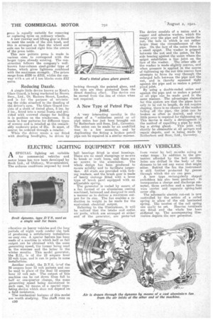
The mechanical features of this model are worth studying. The shaft runs on c30 ball bearings fitted in steel housings. There are no small stainpings or stx•ews to break or work loose, and there are no screws In the aluminium. The whole design has been produced to secure solidity and to facilitate inspee%Ion. All studs are provided with locking washers, and the brush gear is made of heavy castings fitted with a lever type of brush pawl equipped with an adjustable spring. The generator is cooled by means of a fan formed of an aluminium casting machined, balanced and designed in such a manner as to deliver a maximum output for its size. The fan enables a reduction in weight to be made for the equivalent electrical output. Referring to the illustrations, it will be noticed that the intake and outlet, air ports, which are arranged at either end of the generator, are proteated from water by bell mouths acting as water traps. In addition to the protection afforded by the bell mouths, holes are drilled in the body of the dynamo to let out any water that might enter. Behind the fan the instrument is still further protected by gauzes thtough which the air can pass. A new type rectangularly shaped awitohbox has also been produced. It incorporates a charge and discharge ammeter, three switches and a spare fuse wire carrier and separate spring-held cover clip. The automatic electric cut-out is now controlled by the action of a coiled spring in place • of the old laminated spring. The tension of the coil spring can easily be aet. Heavier terminals are fitted and the whole has been stiffened up.. The accompanying illustration depicts the new generator.