


THE LATEST DENNIS PRODUCTION.
Page 22
Page 23
Page 24
If you've noticed an error in this article please click here to report it so we can fix it.
A New Chassis with a Load Capacity of Four Tons, Suitable for a 56-Seated Double-deck Bus, a 36-Seated Single-deck Bus, or a 35-Seated Motor Coach.
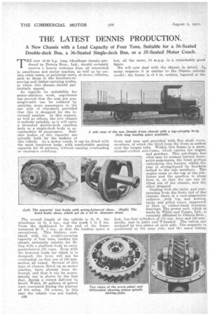
THE new 40-50 h.p. long wheelbase chassis produced by Dennis Bras., Ltd., should certainly receive a hearty welcome from all interested in omnibuses and motor coaches, as well as by certain other users, or potential users, of motor vehicles, such as those in the furniture-removing and timber-carrying trades, to whom this chassis, should particularly appeal.
As regards its suitability for motor-omnibus work, experience has proved that the oast per passenger-mile can be reduced by carrying more passengers in the one unit of transport, provided. that this is designed for the increased number. In this respect, as well as others, the new chassis is entirely suitable, As it will carry a. 50-seated double-deck omnibus body or a single-deck body to accommodate 36 passengers. Suitable bodies of this capacity are actually built by the makers of this vehicle. As a motor coach, it can be fitted with the most luxurious body,with comfortable seating capacity for 35 persons, without causing overloading or excessive overhang.
A side view of
The overall length of the vehicle, is 25 ft., the wheelbase .15 ft. 4 ins., and the track 5 It 6 ins. From the dashboard to the end of the frame measures 20 ft. 3 ins., so that the loading space is exceptional. This feature, combined with its weight-carrying 'capacity of four tons, renders the chassis eminently suta.ble. for fitting with a platform body to carry pantechnicon lift vans. Even with the heaviest loads for which it is designed, the tyres will not -be overloaded, as they are of 130 mm. section all round. Several of this type of chassis, fitted up as motor coaches, have already been delivered, and that it can be economically run is shown by the fact that, during a recent delivery to South Wales, 20 gallons of petrol Were consumed during the journey of 200. miles. Of course, in this case the vehicle was not loaded,
026 but, all the same; 10 m.p.g. is a remarkably good figure.
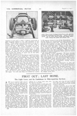
We will now deal with the chassis in detail,. In.. many respects it is similar to the Dennis subsidy model ; the frame is of 8 in. section, tapered at the front and rear and provided with five stout crossmembers, of which the third from the front is arched over the torque tube. Within this frame is a stout, channel-section sub-frame, which carries the eng-ine and gearbox. This sub-frame' has
what may be termed limited threepoint-suspension, the front portion embodying this feature, whilst the rear is strengthened by brackets
• bolted to the side members. The engine rests on the top of the subframe and the gearbox is slung from it, so that the one can be lifted out of the chassis, and the other dropped.
Dealing with the units, and commencing from the front end of the chassis, there is a east-aluminium radiator, .3vith top and bottom tanks and gilled tubes, supported in fibre or rubber-lined trunnion bearings. The power unit, which is
• made by White and Poppe, Ltd., a company affiliated to Dennis Bros., Ltd., has four cylinders of 115 mm. bore and 150 mm. stroke, cast m pairs and. T-headed. The valves are enclosed by two plates at each side. The magneto is positioned at the near side, and the same timing
Pillion drives the fan. pulley. The latter is provided with a leather disc friction clutch, so that sudden acceleration does not cause undue stress on the belt. The water pump is situated at the off side. The carburetter inlet connection is hot-water-jacketed and the carburetter. is of Claudei-Hobsort make.
Lubrication is on the combined pressure a n d ' splash system, a feature being that there are no external pipes beyond that carrying the oil-presaure gauge, which is carried on the engine and not on the dash, although it can be .seen through an orifice in the •latter. The oil pump forces t h lubricant through the hollow camshaft, a relief valve keeping the normal pressure to about 40 lb. per ece in. The front main . bearing is lubricated under pressure, but the others are gravity fed. The big-ends dip into constant level oil troughs. -There is also automatic lubrication of the clutch.
spiget • through the drilled crankshaft.
Drain taps are provided at the lowest points of the water jackets arid pump, so that all the water can he withdrawn in case of frost. Provision is made in the valve caps for a second set of sparking plugs, or for a pressure tester. In the ordinary course, -these holes a, r filled by screwed plugs. in order to test the amount of lubricating oil in the crankcase, a simple dip rod is fitted into the oil-filler cap.
We have not the space at our disposal to go into further detail, but would draw attention to the extreme care taken in the design as is manifested by such devices as the return oil lead from the top of each tappet guide, a passage purposely made tortuous to prevent blow-back. From the engine the drive is taken through a Ferodo-faced cone clutch with three spiral springs, which are most accessible for adjustment. Between the clutch and the gearbox are two Hardy disc joints.
Four speeds forward and a reverse are provided by the gearbox, which is modelled after the subsidy type, with only two selector rods, and wide-toothed pinions, made of heat treated K.E.805 steel, with ground teeth. To prevent hammering down of the comparatively soft aluminium, the ball bearings are carried in steel liners and are protected by thrower rings.
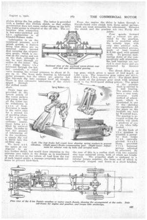
The direct drive is on top gear, which gives a speed of 15.6 m.p.h. at 1,000. r.p.m. The respective gear ratios are 40.1-1, 2e. 2-1, 12.9-1, 7.75-1, reverse 40.1-1. For direct drive the teeth on the primary gear mesh with internal teeth in the third-speed sliding pinion. The spigot of. the primary shaft is carried in a ball bearing. The selector rods have a very neat, serrated teeth method of adjustment, which is illustrated in one of the sketches we reproduce. All the gears on the layshaft are held by Woodruff keys. The gearing is arranged so that the ve,hiele will climb a gradient of one in six when fully loaded.
At the back of the gearbox is situated a powerful foot brake with centrally pivoted brake shoes, provided with balanced springs adjusted by setscrews. At the rear of this.is a cardan shaft with two massive star type universal joints, both of which are totally enclosed. The propeller shaft is enclosed in a tubular torque member, the front end -of which is spherically shaped and bears in a stout bracket;
carried at each end in rubber cushions supported n split housings bolted to the side members of the frame. These rubber-enclosed trunnions form an important part of the arrangement, as they allow a. certain amount of flexibility, and damp cut vibrations and noise. The torque member,. having to take a considerable amount of stress, is very substantially constructed; being turned from a solid forging. In the old days a tube with brazed-on. flanges was employed, but the hammering vibrations. soon caused the speller to spew out at the ends, which then became loose.
The rear axle is driven through an overhead.worm, the final drive gear ratio being 71-1. The axle tubes are of mild steel? case-hardened and ground for the rear wheel floating bushes. The tubes are forced into the main easing under hydraulic pressure. The spring anchorages are free on the axle tubes and are lubricated by surplus oil from the wheel bearings, for which purpose oil -ducts are provided. The ends of the axle tubes are screwed 16 threads per inch, and the wheel holding-on nuts are safeguarded by keyed washers. End play is taken up when necessary by fibre washers, varying, in thickness by -A; in.
The differential gear is of the straight-toothed . type, the planet pinion spindles being a close fit in the cages. At each side they are locked by a plate
in the manner shown in one of the illustrations. The driving shafts are constructed of nickel-chrome steel and are siilined at each end. The wheels are driven through the medium of caps bolted to. them and fitted with hardened steel dowels to take the work of driving from the. bolts. These dowels take the form of sleeves carried on the 'oohs, the bolt holes beingout to a sufficient depth from the opposng faces for their reception. This is a little eXample oh careful designing which must be tested t.) be fully appreciated.
The braking is quite adequate. We have already referred to the foot brake, but we niust mention that the reat brake drums are 22 ins, in diameter. The hand brake is of the internal-expanding type, with remarkably large operating cams. The turning circle is 50 ft., and the steering gear is of the worm. and-sector type, the connections having springloaded ball joints at. each end. A small but important refinement is that. . the change-speed operating shaft, .clutch operating shaft, and hand brake cross-shaft are carried in spherical ' steel trunnions bushed with; phosphor-bronze; thus there is no tendency for them to bind in the case of frame flexion. The front axle is a stout forging, and the front wheels are held on to the stub axles by simple lynch pins.