


New 67 m.p.h. Fire engine
Page 30
If you've noticed an error in this article please click here to report it so we can fix it.
QETTING a high standard of alluiround efficiency, the new Dennis ,F.2
• fire-engine was demonstrated last week • to Press representatives by Dennis Bros., • Ltd., Guildford. As reported in "The .Commercial Motor" last week, a RollsRoyce 150 b.h.p eight-cylindeied in-line engine is used for the Power unit.
To• demonstrate the ease with which the engine cotild be started from cold, the chassis had been left in the open during the previous night, and within a few seconds of pressing the starter button the engine was running smoothly
at a fast, idling speed. This ease of starting, which is essential for theengines, has been accomplished by using a specially designed automatic strangling device.
Immediately the engine was started the appliance was driven away, and had reached nearly 40 m.p.h. within the first 300 yds. On the road, the F.2 displayed a remarkable performance by accelerating to 30 m.p.h. in 15 secs. and to 50 m.p.h. in slightly over 40 secs. Acceleration from 10-30 m.p.h. was accomplished in 19.6 secs.
Restart on 1 in 4 These tests were made with a running weight of 6/ tons, of which 2 tons 16 cwt. represented the stripped chassis weight. At one, period of the test the machine reached 67 m.p.h.. which is the maximum governed speed. Its hillclimbing capabilities were demonstrated on a severe hill, where it climbed a 1-in-4 section at 10 m.p.h. in second gear. No difficulty was experienced in starting from rest on this gradient.
Good braking is essential in fireengines, and the F.2 does not lack stopping power. From 30 m.p.h. the chassis
A28
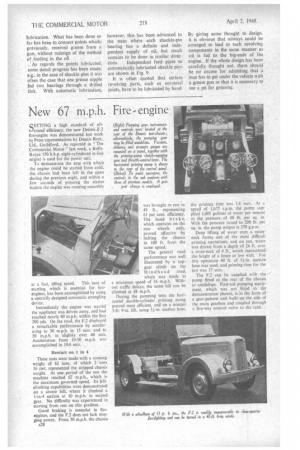
(Right) Pumping gear, instruments and controls were located at the rear of the Dennis test-chassis ;. alternatively, the pumping gear may be fitted amidships. Vacuum, delivery and pressure gauges are mounted on a panel, together with the priming-pump clutch-engaging gear and throttle-control lever. The horizontal priming pump is shown to the rear of the control panel. (Below) To assist operators, the controls in the cab conform with those of previous models. A gate gear change is employed.
was brought to rest in 49 ft., representing 61 per cent. efficiency. The hand brake, which operates on the rear wheels only, proved effective by halting the chassis in 100 ft. from the same speed.
The general road performance was well illustrated by a topgea:r climb on the Hindhead road, which was made at a minimum speed of 34 m.p.h. Without traffic delays, the same hill can be climbed at 48 m.p.h.
During the pumping tests the horizontal double-cylinder priming pump proved most efficient, and on a normal 3-ft. 9-in, lift, using 5i-in. suction hose, the priming time was 1.6 secs. At a speed of 1,675 r.p.m. the pump supplied 1,005 gallons of water per minute at the pressure of 40 lb. per sq. in. With the pressure raised to 200 lb. per sq. in. the pump output is 370 g.p.m.
Deep lifting of water over a swanneck forms one of the most difficult priming .operations, and on test, water was drawn from a depth of 24 ft. over a swan-neck of 4 ft., which represented the-height of a fence or low wall. For this operation 40 ft. of 51-in, suction hose was used, and priming time for the test was 17 secs.
The F.2 can be supplied with the pump fitted at the rear of the chassis or amidships. First-aid pumping equipment, which was not fitted to the demonstration chassis, is in the form of a gear-pattern unit built on the side of the main gearbox and coupled through a five-way control valve to the lank.