


Rubber Suspension Makes Headway
Page 43
If you've noticed an error in this article please click here to report it so we can fix it.
New Scammell System Affords Balanced Suspension Combined with Independent Movement for Pairs of Wheels Arranged in Tandem
SEVERAL important advantages are claimed for a new rubber-suspension system, primarily intended for the four trailing wheels of articulated vehicles, which has just been patented by Scamrnell Lorries, Ltd., Watford. The device possesses the desirable features of the rocking-beam suspension system, but is lighter and cheaper to construct and permits limited independent motion of each wheel. Furthermore, it is compact, especially in respect of width, and allows the vehicle frame to be hung at a low level.
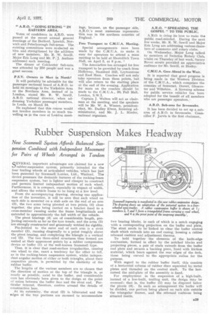
From the accompanying drawing, showing one application of the invention, it will be seen that each wheel on each side is mounted on a stub axle on the end of an arm (3), the two arms being pivoted at two points. (4) close together, the pins being carried on a bracket fixed to a cross-member running under the frame longitudinals and extended to approximately the full width of the vehicle.
The pivot bearings (4) are of considerable length, projecting outwards as far as the tyre treads, and the arms (3) are strongly constructed and generously webbed for rigidity.
Pin-jointed to the outer end of each arm is a strut member (2), running diagonally to a point roughly above the pivot bearing, and completing the triangle is a vertical rod (5). The two three-sided structures thus formed are united at their uppermost points by a rubber compression device or buffer (1) of the well-known Scamraell type.
Thus, it is clear that road-surface irregularities, causing one wheel to rise, exert a tendency for the other to fall, as in the rocking-beam suspension system, whilst independent angular motion of either or both triangles, about their respective pivots, is permitted by the elasticity of the rubber buffer.
The lengths of the various members are so chosen that the direction of motion at the top of the triangle is, as nearly as possible, axial to the buffer, and considerable care has obviously been given to the design at the point of union between the buffer face and the strut end. Particular interest, therefore, centres around the details of construction here.
At its extremity, the strut (2) is bifurcated and the edges of the two portions are recessed to accommodate two bearing blocks, in each of which is a notch engaging with •a corresponding projection on the buffer end plate. The strut needs to be 'forked to clear the buffer central shaft which extends into an end casing, housing a rubber rebound cushion and adjustment thereon.
To hold together the elements of the knife-edge mechanism, formed in effect by the notched blocks and projecting pieces, a pair of studs extends from the buffer end plate and secures a backing piece, lined with friction material, which bears against the rear edges of the fork, these being curved to the appropriate radius for the purpose.
With regard to the rubber buffer itself, this consists of a horizontal column of rubber discs separated by metal plates and threaded on the central shaft. To the lastnamed the mid-plate of the assembly is fixed.
For employment in the suspension of a high-built, instead of a low-built, trailing unit, the design may be reversed ; that is, the buffer (1) may be disposed below the pivots (4). In such an arrangement the buffer will be divided, one portion being placed on each side outside the triangular frames, and the rebound cushions being situated inside.