


Patents Completed.
Page 60
If you've noticed an error in this article please click here to report it so we can fix it.
PUMP ARRANGEMENT—Maims.No. 22,381/06, dated (under Convention) 26th October, 1907.—This invention re
lates to the arrangement of pumps employed in two-cycle explosion motors. The pump cylinders are arranged one on each side of the crankshaft, and they have the same geometrical axis. The pistons (o, 01) are connected to the crankshaft by means of a slot and crank (10). The object of this construction is to minimise space and cost of production.
VEHICLE SPRING.—Pullear Motor Co., Ltd.—No. 13,161, dated 11th June, 1907.—In order to allow a motor body of the maximum width between the wheels,
the upper member of the spring (c) is attached to a cross-member (e) of the body, and the lower portion of the spring is held, or supported, by a bracket (f) formed on the axle (b). The inner part of the hub (h) of the wheel (d) lies within the space between the two portions of
the spring so that, with a good width of wheel base, a maximum width of body is obtained, the spring being fixed as near to the wheel as possible and the body near the springs.
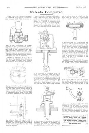
VALVE GEAR.--Gardner and Another. —No. 9,315, dated 22nd April, 1907.—The usual cam (a) on the cam-shaft (b) is tea. used for actuating a valve-operating plunger (c). One end of the thrust piece (e), which is serrated on its upper surface, is connected to the upper end of the plunger (e) by means of a pivoted link (d). The other end of the thrust piece (e) is connected to a locking lever (f) which has a bifurcated lower end and is pivoted to the casing (g) wherein a plunger (e) slides. A striking lever (1), having its pivot pin (j) disposed slightly above its operative end (k), is provided between the thrust piece (e) and the stem (h) of the inlet valve. When the parts are in operation, one side of the thrust piece is raised by the plunger (e), and, thus the required movement is imparted to the valve. By arranging the pivot (j) of the striking lever (i), as before described, the operative cad (k) of the lever is raised and the thrust piece will move in a vertical line and so impart a direct upward pressure to the valve stem (h). For varying the amount of lift, or opening movement, of the valve a rod (1) is connected to the rocking lever (f) so that, under the action of this rod, the point of engagement of the thrust piece (e) with the striking lever (i) is brought nearer to, or moved away from, the point of connection of the rocking lever (f) with the thrust piece (e). Thus, the amount of lift imparted to the valve is diminished or increased as desired. The rod (1) is connected to the governor of the engine.
CARDAN TUBE.—Societh Anonyme des Automobiles Delaunay-Belleville.— No. 21,028, dated (under Convention) 22nd August, 1907.—A tube (D) encloses the cardan shaft and it is attached at one end to the differential casing (C) by means of a flange ; the other end of the
tube carries a ball joint (d). The other member of the ball joint is connected to a bridge (B) by means of an adjustable member (E) and a ball joint (b). The bridge is attached to the chassis (A). In this way a flexible connection is obtained between the tube (D) and the chassis (A).