


Servo Control for Oil-engine Injection Timing
Page 34
If you've noticed an error in this article please click here to report it so we can fix it.
A Résumé of Patent Specifications that Have Recently Been Published
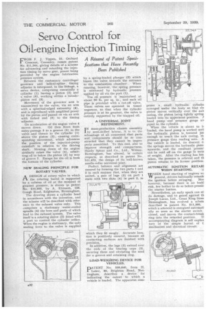
FROMF. J. Tippen, 21, Orchard Crescent, Coventry, comes patent No. 511,344, giving details of a scheme for advancing and retarding the injection timing by servo gear, power being provided by the engine lubrication pressure system.
Between the customary centrifugal governor and helical-spline timing adjuster is interposed, in the linkage, a servo device, comprising essentially a cylinder (1) having a piston (2) and a valve (4), working within a tubular piston rod (3).
Movement of the governor arm is transmitted to the valve, via an arm with a spherical-edged extremity (8), and is reproduced, with amplified power by the piston and passed on via an arm with forked end (9) to the timing adjuster.
On acceleration of the engine valve 4
moves down. Oil then flows from entry:passage 5 to a groove (6) in the valve and thence to the cylinder (1) above the piston (2), causing corresponding movement, which advances the position of the injection-pump camshaft in relation to the driving shaft. Slowing down of the engine similarly raises the valve (4), admitting oil to below the piston (2) by way of groove 7. Escape for the oil is from the bottom of the cylinder.
NEW SEALING PRINCIPLE FOR ROTARY VALVES.
A DESIGN of rotary valve in which
the rotating barrel is supported by a column of oil at the moment of greatest pressure, is shown in patent No. 510,603, by A. Etessam, 128. Gough Road, Edgbaston, Birmingham.
The drawing shows a cylinder head in accordance with the invention, and the scheme will be described with reference to the exhaust valve only. This comprises a stationary water-cooled spindle (4) the bore and ports of which lead to the exhaust system. The valve itself is a rotating sleeve (3) fitted with a port to control the cylinder orifice. When the engine is stationary, the only sealing force to the valve is supplied
by a spring-loaded plunger (2) which biases the valve towards the entrance to the combustion chamber:' . When running, however, the spring pressure is reinforced by hydraulic pressure applied by oil via the port (1).
The oil pressure is maintained at about 50 lb. per sq. in., and each oil pipe is provided with a cut-off valve. These valves are operated in timed sequence, so that when the cylinder pressure is at its greatest, the valve is entirely supported by the trapped oil.
A UNIVERSAL JOINT REFINEMENT.
I N mass-production chassis assembly by semi-skilled labour, it is to the advantage of all concerned that parts and components should be so constructed that they cannot be improperly assembled. To this end, also to improve strength and compactness, Hardy Spicer and Co., Ltd., Witton, Birmingham, has altered, in certain respects, as described in patent No. '511,47_5, the design of its well-known needle-roller universal joint.
Perfect balance and alignment are assured by forming the two parts 1 and 2 in such manner that, when they are united, a pair of lugs (3) on part 1 mate with two slots (4) in part 2, in which they fit snugly. Accurate location is positively ensured, because all contacting surfaces are finished with precision.
In addition, the lugs (3) extend over the ends of the bearing cups (5), securing these and obviating the need for a groove and retaining ring.
LOAD-WEIGHING DEVICE FOR VEHICLES.
PATENT No. 509,640, from H. Laker, 65, Brighton Road, Nottingham, describes a device for indicating the extent to which a vehicle is loaded. The apparatus coin prises a • small • hydraulic cylindei arranged under the body so that thc piston moves, vertically over the writ casing, the piston being lightly spring loaded into its uppermost-position. A hand pump and pressure gauge an piped to the cylinder.
When the vehicle is about to b. loaded, the hand pump is worked unti the hydraulic piston is. lowered jus enough to touch the axle casing, th pressure gauge then reading zero. A the vehicle is loaded, its descent o; the springs moves the hydraulic Pisto; upwards, and the resultant press': can be read off on the gauge in term of weight. After the reading has bee taken, the pressure is relieved and th piston returns to its former position.
AUTOMATIC IGNITION RETAR1 WHEN STARTING.
WHEN hand starting of engines wc YV general, drivers habitually retarde the ignition before swinging. Nov however, because there is no bodil risk, few bother to do so before pressir the starter button.
Nevertheless, an early spark can sti do damage, and to guard against th Joseph Lucas, Ltd., Great King Stree Birmingham, has evolved a schein described in patent No. 511,360, which a solenoid is energized automati ally so soon as the starter switch closed, and moves the contact-break ring ;into the retarded position. TI accompanying diagram is self explan tory of the simple layout of t: mechanism and electrical circuit.