


A MAUDSLAY FOR A DOUBLE-DECK BUS.
Page 9
Page 10
If you've noticed an error in this article please click here to report it so we can fix it.
A Low Level to the Frame and the Use of an Underslung Worm Serve to Provide a Chassis Suitable for a 54-Seater Double-deck Bus With Shelter to the Top Deck.
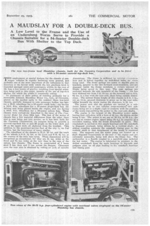
• TILL, employment of special designs for the chassis of pas senger vehicles is rapidly becoming more general, and probably one of the most important of the influences in that direction is The favour with which the low platform level is regarded amongst users and passengers, whilst, in the case of the bus, a low centre of gravity, resulting from special attention being paid to this point, permits of the use of top-deck shelter, for which the public is constantly asking.
• In pursuance of their policy of catering promptly for a reasonable demand, 1Vlaudslay Motor Co., Ltd., of Coventry, placed on the market early in the summer three low-level chassis, specially designed to take passenger bodies, one having a 15-ft. wheelbase for a 22-seater coach body ; one having a 16-ft. 6-in, wheelbase for a 37-seater single-deck bus, the driving, seat being placed beside the ebgine, and one having' a 16-ft. 8-in, wheelbase for a 80-seater saloon bus. These chassis were exclusively described in the issue of The Cornmecial Motor for June 16th last. The last of the series of chassis has a few material differences from the other three And is now being put into service, as it has been built for the Coventry Corporation, its purpose being to provide a covered top-deck bus to seat 26 people on the lower deck and 28 on the upper deck, all sheltered from the weather. This addition to the passenger-service feet of the city 1.L.;, we feel certain, but the forerunner of many similar.
The wheelbase of the chassis is 15 ft. 10 ins, and the track of the wheels is 6 ft. 31 ins, at the front and 6 ft. 41 ins, at the centres of the twin rear tyres. These dimensions will be, recognised as exceptional, for they are 31 ins, wider at the front and 71 ins, wider at the rear than in the ease of the saloon bus chassis. The frame is constructed of I beam steel 6 ins, deep and 3 ins, across the flanges. Clearance over the rear axle is obtained by rolling an arch of suitable dimensions. The frame is stiffened by talialar rrers-mr.mhers and is bolted together by well-fitted bolts, no rivets being used. The front swings are taken to shackle pins in brackets, secured to the two forward cross-members, and are disposed inside the frame members, a certain • amount of height being saved in this way. The rear springs are mounted beneath the side members of the frame, ich has been widenedDui-, from 2 ft. 10 ins, at the forward end to 4 ft. 91 ins, in a line with the rear axle, these being outside dimensions. The normal frame height of this chassis is 2 ft. 1 in., yet an 11-in, ground clearance is given up to the rear axle, whilst beneath the worm casing the clearance is 81 ins.
The power nnit and the gearbox are carried on a sub frame bolted up to two tubular cross-membere, this subframe being set at a slight angle to conform with the position of.the worm transmitting the power to the rear axle shafts.
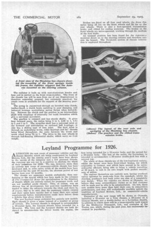
The engine is the largest of the Matidslay power units, having four cylinders, with a bore of 41 ins., the piston stroke being 6 inS. The power is set out at 36 h.p. to 75 h.p., the one pat at normal engine speed being 50 h.p.It eensists of a naonohloô casting, with the heads detachable in pairs. The crankshaft is carried in five ample bearings-and till camshaft is disposed overhead, being driven by a vertical shaft. .A . sliding•coupling connects the camshaft timing gear to the vertical shaft so that detachment of the heads is rendered easy. The magneto and the water pump are located on a shaft disposed transversely at the rear of the engine and are extremely accessible, being well above the frame line. The carbaretter is a Zenith coupled to a manifold pipe jacketed for hot water. The engine is lubricated by pressure to the drilled crankshaft from the main bearings to big-ends and gudgeon pins, an Gil pipe leading to the camshaft, bearings and timing gear.
The radiator is built up with cast-aluminium header and base and is carried on the front cross-member. The front of the chassis (as will be seen from one of our illustrations) is therefore somewhat unusual, but extremely practical, for ample room is available for the support of the steering gearbox.
The power is ...-ransmitted through an inverted cone clutch, leather-faced, a clutch brake assisting in gear changing, and balanced leverage neutralising spring thrust when declutching. Between the clutch and the gearbox is an intermediate shaft with couplings of internally cut tooth formation which give a universal movement.
The gearbox is compact and has sturdy shafts. It gives four forward gears, the ratios being 5 to 1, 2.88 to 1,.73 to 1 and 1 to 1. The propeller shaft has a universal joint at the forward end articulating on enclosed ball 13..arings; it also has a sliding type of rear joint. The final drive is through an undersIttng worm, roller bearings and ha!! thrusts being fitted throughout, the ratio between the worm and worm wheel being 71 to 1. The drive to the rear wheels is through full-floating differential shafts, which carry no dead weight.
Brakes are fitted on all four road wheels, the drum diameter being 18 ins. on the front wheels and 24 ins on the rear wheels. There is also a foot-operated transmission brake, well ribbed for cooling purposes. The brakes on the front wheels are servo-operated, working through the medium of the foot brake.
An unusual position has been found for the Antovacmounted direct on to the steering column and therefore outside the bonnet. The Tecalornit system of chassis lubrication is employed throughout.