


A Heavy-duty Tractor
Page 60
If you've noticed an error in this article please click here to report it so we can fix it.
,r1
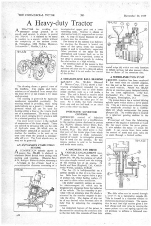
A TRACTOR for working over extremely rough ground, or in marsh and swamp, is shown in patent No. 784,436. It is claimed to be equal in traction to a crawler vehicle without the complexity of the endless tracks. (J. Thibodeau, 5001 Phillips Highway, Jacksonville 7. Florida, U.S.A.)
The drawing shows a general view of the machine. The engine and transmission are of standard form, except that the final drive to the wheels is by chain and sprocket.
The steering is powered by hydraulic mechanism controlled electrically. No steering. wheel is provided, there being push-buttons on a panel (I) instead. A powered winch (2) can be used for hauling either a load or the vehicle itself out of a predicament. The winch is fitted with a short swinging jib (3) which is held in a selected position by chains.
The most novel feature is the method of suspension of the front wheels. These are carried by swinging links on the ends of hydraulic rams (4) which can be individually extended as required. This enables the machine to be used on an even keel when the ground is considerably off level. The front wheels may or may not be powered.
AN ANTI-KNOCK COMBUSTION SCHEME COMBUSTION scheme shown in patent No. 784,481 is claimed . to eliminate Diesel knock both during cold starting and running. (Daimler-Benz A.G., Stuttgart Untertiirkheim, Germany.) Arranged in the .cylinder head is a pre-combustion chamber consisting of a
hemispherical upper part and a lower restricting neck. Midway is placed an obstructive body (I) supported on a crosspin. A loop of heater filament (2) also projects into the chamber.
The theory of the scheme is as follows: for starting, the filament is heated and some of the spray from the injector strikes it and is immediately vaporized. Other portions of the spray hit the obstruction and bounce back on to the filament, this too is vaporized. Some of the spray is atomized purely by striking the obstruction at a high velocity.
An essential part of the patent is that the heater filament is automatically switched off after use by a delayed-action device so that it is not under the control of the driver.
A STRAIGHT-LINE BALL BEARING
PATENT No. 781,846 (General Motors Corp., U.S.A.) shows a ballbearing arrangement intended for use when one member has to slide freely inside another, such as a rod inside a tube. The rod is fluted to receive axial rows of balls, whilst the tube may also be fluted to form the other part of the race. As it slides, the balls emerging from one end are led back to an entry port at the other via ducts.
PNEUMATIC GOVERNOR CONTROL
I MPROVED control of injection pumps is claimed for a modification to the suction system disclosed in patent No. 782,934. (Simms Motor Units, Ltd., and Z. Miracki, both of Oak Lane, London, N.2.) The chief point is that that part of the intake pipe from which suction is taken is made rectangular instead of round. A rectangular pivoted flap is used for the throttle. By this means, suction is said to be increased and made more stable.
A MAGNETIC FAN DRIVE
A VARIABLE-ENGAGEMENT magi' netic drive forms the subject of patent No. 784,192, the purpose of which is to give simple control over the driving of the cooling fan of an engine. (S. Smith and Sons (England), Ltd., Cricklewood Works, London, N.W.2.)
The fan (1) is ball-journalled on a central spindle so that it is a free member. Belts from the engine drive a pair of pulleys (2), whilst further pulleys (3) are used to drive other auxiliaries.
The pulley assembly carries an annular electro-magnet (4) which can be progressively energized from the batteries of the vehicle. The fan assembly is provided with an armature disc (5) which is attracted by the annular magnet to provide the drive. The degree of slip can be of any desired value between zero or fully free by adjusting the energizing current.
An important feature of the patent is the means for attaching the armature disc to the fan hub; this consists of four thin metal strips (6) which not only function as return springs but also prevent vibration or flutter of the armature disc.
A PETROL-INJECTION PUMP DETROL injection has been employed I for some time on aircraft engines, but has not so far come into wide use on road vehicles. Patent No 784,425 shows an injection pump designed mainly for the latter application. (The S.U. Carburetter Co., • Ltd., Wood Lane, Erdington, Birmingham, 24.)
The pump shown has a vertical driving spindle upon which slides a servo piston (1). This, as it moves up or down, varies the amplitude provided by a wobbleplate (2) which reciprocates the pump plungers (3). The wobble-plate is located in a spherical guiding stirface in the casing.
Pressurized oil from the lubricating system of the engine is admitted at 4 and fills the space above the servo piston. It also reaches the space (5) inside the shaft. It can escape from there under the control of ports and slide valve (6) to drain through a limited orifice.
The slide valve can be moved through a lever (7) by a barometric capsule (8). This is housed in a chamber subject to induction-manifold pressure. The operation is such that high suction gives a low fuel charge and vice versa by moving the servo piston via a coil spring against the oil pressure to achieve a balanced condition.