


A Three-ratio Torque Converter
Page 60
If you've noticed an error in this article please click here to report it so we can fix it.
A Risume of Recently Published Patent Specifications
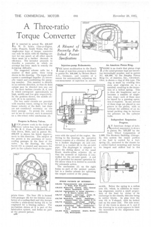
I T is asserted in patent No. 435,647 by W. D. Sykes, Clan-yr-Eigion, Sully, Penarth, South Wales, that the single-rotor type of torque converter can only be made with its blading correct for one speed; at all other speeds there must be a further . decrease in efficiency. The inventor proceeds to describe a converter in which an attempt has been made tc remedy the foregoing difficulty.
The suggested scheme calls for a number of fluid paths, three being shown in the drawing. The input shaft carries a centrifugal impeller (I) internally vaned and constituting the pumping member. This member is slida.ble in an endwise direction, so that its fluid output may be directed into any one of the three turbine circuits (3, 4, and 5) which correspond pproximately to high, middle and low gear respectively. In the position shown, the middle circuit (4) is in operation.
The two outer circuits are provided with reaction vanes, owing to the high linear velocity of the fluid, but these are not considered necessary on the inner passage. To permit the rotors not in use to overrun, each is mounted on a free-wheel roller mechanism (2).
Progress in Rotary Valves.
MUCH pioneer work in the design of rotary valves has been carried out by Mr. R. C. Cross,33, liefidford Road, Odd DOW11, Bath, and in patent No. 436,117 is shown his latest improvement in this direction. The subject of the patent is the provision of watercooling passages in the liner of the valve. In the drawing, the valve barrel (1) is rotated and uncovers the port in the cylinder head at the appro priate times. The liner (5) is formed with passages (4) for the interior circulation of a cooling fluid and this feature enables a white-metal facing (3) to be employed for a bearing surface. The mechanism shown at 2 is part of the lubrication system, and forms no part of the present. patent.
u46 Injection-pump Refinements.
THE latest modification to the Bosch range of injection pumps is described in patent No. 435,596, by Robert Bosch A.G., Germany, and consists of a means for automatically adjusting the commencement of injection in accord ance with the speed of the engine. Referring to the drawing, the operative means consists of a chamber (5) closed by a leather diaphragm (4) and connected to a venturi (6) in the air-inlet pipe. The diaphragm is adapted to move the sliding sleeve of the usual Bosch double-spline adjuster (3), so that the moment of injection is controlled by the air-inlet speed. A rod (2) is provided for manual operation by the driver when it is desired to override the automatic action.
The mechanism (1) on the right forms no part of the present patent, but is a similar Scheme for operating the output control of the pump. An American Piston Ring.
THERE is no doubt that piston rings 1 id the axial-pressure type are becoming increasingly popular, and in patent No. 435,359, by the Simplex Piston Ring Co. of America, Inc., Cleveland, Ohio, is shown a ring of this type. The ring is made by winding thin strip steel edgewise on to a: mandrel, resulting in the formation of a helical spring. This is then slit lengthwise and so becomes a number of singleturn rings ; each of these may be biased by a pressing operation if required. In use, several of these rings are placed in one. groove in the piston, with or without the addition of an in-; ternal packing ring to increase the pressure on the cylinder walls.
Independent Suspension Progress,
AN American design of independent suspension is shown in patent No. 435,227 by the Steel Wheel Corporation of 1,060, The Rookery Building, Chicago. In this system the major portion of the load is carried by a leafspring (2), anchored to the chassis by a rubber-bushed mounting and having its longest and stiffest leaf in tha
middle. Below the spring is a radius arm (3), which, in addition to ensuring alignment, carries a small proportion of the load by virtue of its anchorage to the chassis, this also being in rubber blocks. In plan view the arm (3) is Y-shaped, with its forked end on the inner side. The side member of the frame is shown at 1, and if the drawing be to scale appears to limit the movement of the suspension considerably