


A NEW FORM OF CONE CLUTCH.
Page 78
If you've noticed an error in this article please click here to report it so we can fix it.
TEE cone clutch is still capable of holding its own, if wo may judge from the fact that such a well-known name as that of Louis Renault is associated with patent No. 269,850, which is for improvements in cone clutches. In the present ease the fly-wheel is formed so that there is no contact between it and the leather-covered cone. Instead, to the edge of the flywheel is attached a conical member projecting inward. A cone, which may be made from a pressing of sheet metal, carries a lining of leather or other suitable
material, and by a rearward movement comes into frictional contact with the cone attached to the flywheel.
The special feature of the invention is that it provides a clutch which will engage softly at first, increasing its grip as it increases its speed. The member which is attached to the flywheel is interrupted in places to receive segmental portions, which are held in place by means of studs and springs. These springs are en arranged that when centrifugal force exceeds the tension of the springs, a slight outward movement of the segments shall take place. The segments, being attached to the flywheel, which is the driver, can, by an increase of the speed of the engine, be made to fly slightly outwards, so producing a soft engagement of the clutch, and as the cone is pressed inwards they can return, to their original places, but as speed increases centrifugal force will help them to grip.
Relating to Sleeve-valve Engines.
THE name of Marry Ralph Ricardo,
already well known in connection with engine design, appears in patent No. 279,176 in connection with an engine of the single sleeve-valve type. The speeification points out that, hitherto, in such engines, when the cylinder block was removed, there -was difficulty in retiming the gear mechanism which operated the move, ment of the sleeves, owing to the fact that the revolving members which imparted the sliding and rolling movement to the sleeve were disconnected from their driving shafts when the cylinder block was raised. In the present instance the shaft which operates the revolving members has its bearings formed integral with the cylinder block, consequently there is no need to disengage its gears from those on the valve-actuating members.
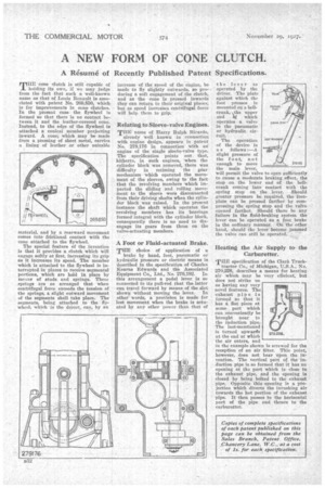
A Foot or Fluid-actuated Brake.
THE choice of application of a
brake by hand, foot, pneumatic or hydraulic pressure or electric means is described in the specification of Charles Kearns Edwards and the Associated Equipment Co., Ltd., No. 279,192. In this arrangement a pedal lever is so connected to its pull-rod that the latter can travel forward by means of the slot shown without moving the lever. In other words, a provision is made for lost movement when the brake is actuated by any other power than that of the lever as operated by the driver. The plate against which the foot presses is _mounted on a bellcrank, the upper end operates a valve in the pneumatic or hydraulic circuit.
The operation of the device is a s follows :—A slight pressure of the foot, not enough to move the main lever,
will permit the valve to open sufficiently to cause a moderate braking effect, the Step on the lower end of the bellcrank coming into contact with the spring stop on the lever. Should greater pressure be required, the footplate can be pressed farther by compressing the spring stop and the valve opened farther. Should there be any failure in the fluid-braking system the lever can be operated as a foot brake in the ordinary manner. On the other hand, should the lever become jammed the valve can still be operated.
Heating the Air Supply tothe Carburetter.
THE specification of the Clark Truck tractor Co., of Michigan, No. 270,228, describes a means for heating air which may be very efficient, but does not strike us as having any very novel features. The exhaust pipe is formed so that it has a flat piece at some part which can conveniently be brought near to the induction pipe. The last-mentioned is turned unwards at the end at which the air enters, and in the example shawl is screwed for the reception of an air filter. This point, however, does not bear upon the invention. The vertical part of the induction pipe is so formed that it has an opening at the part which is close to the exhaust pipe, and the opening is dosed by being bolted to the exhaust pipe. Opposite this, opening is a projection which diverts the inruahing air towards the hot portion of the exhaust Pipe. It then passes to the horizontal part of the pipe and thence to the carburetter.