


MAKING BEST USE OF THE FORD.
Page 77
If you've noticed an error in this article please click here to report it so we can fix it.
Valuable Advice on Every Phase of Ford Transport which will Appeal to the Owner, Driver and Repairer.
557.—Relining Transmission Bands.
After relining a transmission band freguent , adjustments are often necessary, but the number of these -can be lessened to a considerable extent if the linings be put on in the following manner :— First, secure the ends, allowing the lining to bulge out slightly from the band in the manner illustrated. The bulge is then hammered down, the hammering being, Carried round the band towards the points whore it is secured, and after the remainder of the riveting has been finished, a very snug fit will result. In addition, the hammering, which, of course, should not be carried to excess, tends to harden the lining and will ensure a better working life.
558.—Concerning Broken Crankcase Arms.
A Ford tonner engaged upon general haulage work involving the conveying of heavy loads over bad roads will occasionally break one of the crankcase arms on the sides Of the transmission case. As•this causes the engine to drop several inches on the side that the arm is broken, it is inadvisable to attempt to drive the truck any farther.
The only replacement listed in the Ford spare parts. list is the standard arm, which has to be riveted and brazed on. There are, however, several replacement arms on the market. .These are made from boiler-plate steel, cost approximately 38. retail, awl are usually to be obtained from the local Ford dealer. They make very satisfactory substitutes and avoid the necessity of removing the crankcase when fitting. According to the makers these arms can be fitted in a few minutes without any alteration, and by unskilled labour. This happy state of affairs, however, only happens once in a while.
The repair man should prepare for breakdowns of this description by keeping two or three of these arms by him— they are interchangeable right and left —a few crankcase-arm bolts (top, as fitted to models of 1026 and onwards) and a few crankcase-to-cylinder baits. A .small hole should be drilled through the head of each bolt to enable a locking wire to be passed through it.
Unlesa it be definitely known which side arm he broken, and whether a starter or non-starter-type transmission case be fitted, the repair man should take with him two each of the cylinderto-crankcase bolts and the crankcasearm bolts. Half-a-dozen 4-in. plain washers, a few spring washers, a finebladed hacksaw, and a good chisel. A tommy bar and jack should also be iii chided in the kit.
. Nine times out of ten the arm will be found to have broken in such a position that the remaining portion On the crankcase will foul the replacementarm legs and prevent them from lining up with the bolt holes. If a transverse cut be made with the hacksaw and
chisel across the remaining portion of the arm—as near the top as possible, the projections can be turned inwards towards each other by dint of hammering.
Having removed the broken half of the arm, lift the engine by placing a jack under the crankcase drain plug and run out the two bolts or setscrews where the replacement arm will be fitted. Position replacement arm. If the crankcase be fitted with crankcase-flange reinforcement plates, position two 1-in. plain washers between the legs of the replacement arm and the crankcase before inserting bolt or setscrew. When there is no reinforcement plate, use three washers to each hole. If this be not done all the weight and strain will be taken by the turned-over lip of the crankcase, and a crack, accompanied by an oil leakage, may result.
When the breakage oeciars on the starter side of a starter-type transmission case the two setscrews normally used Will he found too short to hold the replacement arm. The
crankcase-to-cylinder-block bolts which have been drilled across the head should be substituted for the shorter setscrews and tightened so far as possible, both then being wired together.
On the other side, the standard bolts should be replaced by the longer crankease-arm top bolts.
559.—Stubborn Swivel Pins.
The hexagon heads of Ford swivel pins are somewhat small, and owing to this it is sometimes found a difficult matter to unscrew them, as the spanner slips and rounds the corners. A certain way out of the difficulty is to employ a strong parallel-jaw vice, which, if necessary, can be removed from a bench for the purpose. This should be inverted and used as a spanner by screwing the jaws tightly on to the flats of each head in turn.
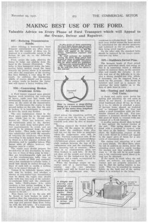
560.—Testing and Adjusting Coil Units.
A cheap and easily made device for testing and adjusting the coil units is shown in our sketch. It consists of a wood baseboard about 10 ins. by 6 ins. by a in., to which is attached a piece of springy brass shaped as depicted and so arranged that the free end makes a good connection with the lowtension contact on the coil. For convenience a terminal should be fitted to this piece of brass to connect with one terminal of a 6-volt battery.
A smaller spring should then be fixed to bear against the bottom 'contact of the coil. This spring should also be fitted with a terminal to connect with the other, on the battery. Immediately above the high-tension contact of the coil a hole should be drilled' and tapped in the upper piece of brass for a setscrew of convenient size.
The testing and adjusting of 'a coil are quite simple. To -effect them, place the coil in position as shown, lower the adjusting screw until it nearly touches the contact and then gradually withdraw it. If the coil be in good condition, a fat, continuous spark about in. long can be obtained.
If the spark be weak when the coil points are unburnt, are making good contact and are properly adjusted, it may be that the spring tension is too weak. This can be remedied by tapping lightly on the back end of the spring where it is attached to the bridge.