


A NEW GEARBOXLESS TRANSMISSION.
Page 67
Page 68
If you've noticed an error in this article please click here to report it so we can fix it.
The Spontan Automatic Infinitely Variable-speed Transmission Mechanism, Giving Utter Simplicity in Driving.
THE Spontan transmission gear, now on exhibition at the Commercial Motor Show, is the invention of Mr. F. Ljungstriim, a Swedish engineer, of A.ktiebolaget Spontan, Stockholm. The invention in itself is most ingenious and the way in which it has been carried out shows great engineering skill on the part of its designer. In its present form it is applicable to private cars and, perhaps, to light vans, but we should like to gee more of it before expressing any opinion as to its suitability for the heavier class of motor vehicle. By the courtesy of the inventor we were enabled, the other day, to make a sonie-: what short road test of the device 'fitted to a private car of moderate power. This run Consisted of a few miles, mostly in congested traffic and including one moderately steep hill. Short as the test run was, however, we were able to see that the gear contained features which we have not hitherto found combined in one device 'of the kind.
Every operation necessary for the control of the car, excepting, of course, the steering, is performed by a single -pedal. The brakes are normally in the " on ".position when the pedal is not-depressed by the.foot, but a slight pressure on the pedal actuates a cam, which operates against a lever and holds the brakes off. Further pressure on the pedal acts as with an ordinary accelerator and increases the speed of the engine, whilst the ratio between-. the engine and the transmission shaft to therear wheels is automatically determined and controlled by the mechanism itself, which regulates the output of power of the engine in relation to the .resistance to movement, such as inertia when starting or the climbing b a . hill. Coasting can be .indalged in whenever desired, arid, to cheek the speed of the Car, one has only to let the pedal rise to a point where the desired degree of retardation is obtained.
A Near Approach to Steam Car Action.
The riding in the car on which we were given a trial resembled drives we have had in the past in steam cars, wherc there was no changing from gear to gear. After starting, as the engine gains speed and the inertia of the car is gradually overcome, the speed of the car gradually increases until the equivalent of top gear is obtained, when, so long as the resistance to movement is norro,al, as with a level road, and the output of the engine is at its greatest, the car will be making its maximum speed. Should the resistance be increased, as when a hill has to be climbed, the ratio of engine to road wheels will automatically alter itself to suit the conditions and the ratio will continue to reduce until the lowest is reached, which we are told will enable a ear to climb a hill of one in four.
When driving in traffic and attempting to take advauSage of an opening the automate, acceleration is more rapid than that obtained by the ordinary method; where one has to change from gear to gear. During our trial we had an. opportunity of seeing how suddenly the brake can be actuated, as a very sudden stop was necessary to avoid running rover some careless_pedestrians who stepped off the pavement right in front of the ear.
Accurately to describe the mechanism by which these results are obtained is not an easy matter, as the drawings obtainable are'-not complete, and We were not able to inspect all the parts which form the gear. Our description must, therefore, be taken as illustrative of the principle, rather than as an actual description, of the working parts.
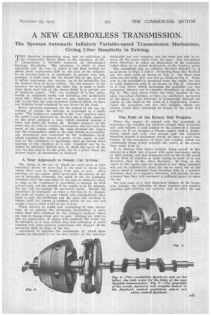
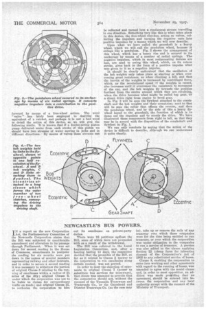
The crankshaft has an ordinary . flywheel attached to it as is shown in Figs. 1 and 2. Projecting from this flywheel are two stub axles as shown in Pig. 1, On these stub axles are two links (C) and (0) as shown in Fig. 4. What acts as the gearshaft is separated from the crank, but lies in axial alignment with it, as shown in Fig. 2. Attached to a long sleeve which surrounds the gearshaft arc two eecentries, thrown out in opposite directions, as shown in Fig. 4. The long sleeve forms the outer member of two roller free-wheel clutches, So that any oscillatory movement of the sleeve in one direction is transmitted through the rollers to the shaft in the form of a step-by-step motion. Upon the eccentrics are two bob weights, which can revolve roundtheir eccentrics by means of the links (C) and (D)..
The Path -of the Rotary Bob Weights.
When the engine is started and the' gearshaft is stationary the weights are revolved around their eccentrics and each follows a path similar to the piston of a Gnome engine; so, if we imagine a gnome engine with a doublethrow crank and only two pistons and the cylinders revolving around a stationary crank; we have a good illustration of the movement of these bob weights, which are continually being jerked towards the centre of the Crank, then away from it.
It is obvious that heavy weights being moved in this manner at a high rate of speed will resist movement, owing to their inertia and this resistance will be felt in the crank in the form of reaction or jerks trying to move it in one direction, than in the other direction. So long as the speed of the 'eagine and its flywheel is low these impulses will not be sufficient to cause the car to move, but as the engine speed is increased these impulses, first in a positive direction, then in a negative direction, will become so pronounced that they will represent a sufficient power to move the ear.
We now come to a very important feature of the invention, namely, the collecting of these negative and positive impulses and utilizing the positive ones to drive the car forward by means of a free-wheel action. The word " valve" has lately been ,employed to describe the equivalent of a ratchet, and perhaps it is not a bad word to detail the action of this device, so we will give the following simile. It is known that if a double-acting piston pump delivered water from each stroke of this piston we should have two streams of water moving in jerks and in different directions. By means of valves these streams can
be collected and turned into a continuous stream travelling in one direction. Something very like this is what takes place in this device, the free-wheel clutches, acting as valves, collecting the impulses and turning the negative ones into positive impulses by a means which we will now describe.
Upon what we have called the gearshaft is a heavy wheel, which we will call the pendulum wheel, because it swings like a pendulum. Fig. 3 shows the arrangement of this wheel, which has a heavy rim and is secured to its anchorage by means of a number of radial springs. The negative impulses, which in most reciprocating devices are lost, are used to swing this wheel, whieln on its return stroke, gives back in the form of a positive impulse what was given to it as a negative impulse.
It should be clearly understood that the oscillation of the bob weights only takes place at starting or when overcoming great resistance, as when climbing a hill, and that the inertia of the weights is increased by centrifugal force, which, as the revolutional speed of the weights is raised, also increases until it overcomes the resistance to movement of the car, and the bob weights fly towards the position farthest from the centre around which they are revolving, when the drive becomes what might be called top gear, or a direct drive right from engine to bevel gear.
In Fig. 2 will be seen the flywheel attached to the crankshaft and the bob weights and their eccentrics; next to that will be seen the collar that effects the reverse, and then the pendulum wheel, and by the side of this a heavy flywheel keyed to the gearshaft, the function of which is to damp out the impulses and to steady the drive. We have illustrated these components from right to left, so that they may be in accord with the disposition of the crankshaft and flywheel in Fig. 1.
We can only conclude by saying that the action of the device is difficult to describe, althengh we can understand it quite clearly.