


ROADSIDE AND GARAGE.
Page 31
If you've noticed an error in this article please click here to report it so we can fix it.
A Page for Drivers, Mechanics and Foremen.
A.E.C. Improvements.
The sender of the following communication has bees awarded the extra. payment of 5s. this week.
(2323) " E.A." (Barnsley) writes :— "The following notes and the accompanying drawings describe and illustrate some improvements which I have effected in the case of a couple of Tylor-engined A.E.C. chars-ii:banes, and I should say nine out of every dozen A.E.C.s which I have seen were fitted with Tylor engines. I feel sure that the information embodied will be of assistance to several oi your readers. may add that the improve--meats which I have -effected have been copied by other owners of the same type of vehicles in this district, with considerable success.
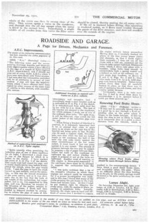
'Quite recently when examining the induction pipe of one of these machines for air leaks, I discovered a crack close to one of the flanges by which it is bolted to the engine. I have marked the point at A on Fig. 1 of the sketch. This crack went half round the pipe, and it would clearly not be long before it completed the circuit, when the pipe would break. I sent the pipe to have the crack burned up (not welded), and in the meantime, as this was the second occurrence of the same nature, and as it was obviously due to the fact that the bulk of the weight of the carburetter, hot water jacket, and so on, was supported by this pipe, and was, therefore, on account of the vibration of the engine, subject to considerable stress, I there and then decided to improve matters by arranging to relieve the pipe of some of this
unnecessary and excessive load. I accordingly made a steel bracket such as is indicated at E on Fig. 1 of the sketch. It is manufactured from mild steel bar ins, wide by I in. thick. The feet of the bracket are secured to the crankcase, for which purpose I made use of two of the ordinary joint bolts, 'The split strap,. will be observed, clips round the hot water jacket of the induction pipe near the top.
"When fixing a bracket of this kind in position, it is extremely important that it he so erected that when in place' there is no strain on the pipe due to the bracket not being quite in line. Readers who fit such a support, must, therefore, take care that when the feet are bolted firmly to the crankcase the half cf the split clip just rests nicely against the miter circumference of the hot water jacket, it must touch it but not press against it to any extent. The amount of pressure between the two may be judged by popping a slip of paper between them, before the bolts on the crankcase are tightened bp, and noting whether the paper is gripped or not as the bolts are tightened. Another word of -naming, as this engine is three-point-suspended in the sub-frame there must be no attempt to support the carburetten from the latter.
"11 was quite confident that a lot of the excessive vibration to which these engines are subject could be accounted for if a. proper investigation was made, and in this case I found that many of the rivets securing the sub-frame to the rain frame had become loose. At first I tried to put matters right by chipping the rivets away, with the engine in place, intending to substitute bolts. Actually, however, the rivets were so hard and difficult of acmes that I doAtipel tn. pmove the engine entirely hetore proceeding. Having done so, I carefully marked the places of the four corner -gusset plates and channels, so that I could replace them correctly; I then cut out all the rivets with a cold set, reamered out the holes,to take turned half-inch Whitworth bolts, which I drove into place with a hammer, using bolts long enough to accommodate both a spring washer arid a locknut as well as the ordinary out. I next made four brackets, as shown in 13 and C of Figs. No. 2 and 3; these were made from 2 in. by a in. mild steel, and were bent to template. 13efore being bolted down they were all carefully bedded in place, so that there was re risk.of springing the.sub-frame, and thus causing initial .stresses. '• Incidentally, since in. nuts were too big, I had to dress them down to accommodate a 1.7.6 in. spanner beforeI conld get them screwed up."
Renewing Ford Brake Shoes.
(2324) "T:B." (Oldham) writes:— " It may not be generally known that it is .a good tip to saw through a Ford expanding shoe at the point where it binges on the brake fulcrum. If this be done the shoe is not so likely to break, as it frequently does at a point a short -distance from the fulcrum, which is
marked in theaccompanying sketch. I have fitted a good many brake shoes, and invariably adopt this plan. There i,s no difficulty about the shoe holding on to its pin, as the pinion springs would be found to be quite satisfactory for that purpose."
Lamps Might.
On Saturday December 3rd, light your lamps at 4.22 in London, 4.9 m Newcastle, 4.25 in Birmingham, 4.10 in Edinburgh, 4.24 in Liverpool, 4.32 in Bristol, and .5.7 in Dublin.