


• WHY CARRY THE LOAI OUR WHEELS ONLY?
Page 14
Page 15
If you've noticed an error in this article please click here to report it so we can fix it.
A New Six-wheeler with Excellent Mechanical Ideal Load Distribution Intended A Further Step Along the Road to the rear and Tear of the Highway.
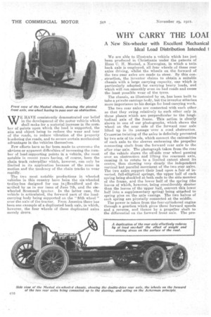
WE HAVE consistently demonstrated our belief in the development of the motor vehicle which shall make for a material increase in the number of points upon which the load is supported, the aim and object being to reduce the wear and tear of the roads, to reduce vibration of the property bordering the roads, and to secure certain mechanical advantages in the Vehicles themselves.
Few efforts have so far been made to overcome the obvious or apparent difficulties of increasing the number of load-supporting points in a vehicle., the most notable in recent years having, of course, been the chain track caterpillar which, however, can only be limited in its application because of the noise in motion and the tendency of the chain tracks to wear rapidly.
The two most notable productions in wheeled vehicles in this country have been the six-wheeled trolley-bus designed for use in !Bradford and described by us in our issue of June 7th, and the sirwheeled Scammell txactor. In the latter case, the vehicle is articulated, the forward part of the loadcarrying body being supported on the "fifth wheel" over the axle of the tractor. From America there has been one example of a duplicated back axle, in which, however, the four wheels of these duplicated axles merely drove. We are able to illustrate a vehicle which has just been produced in Christiania under the patents of Hans C. H. Mustad, a Norwegian, in which a twin back axle is employed, all four wheels of these rear axles driving, whilst the wheels on. the forward of the two rear axles are made to steer. By this con
struction, the inventor claims to obtain a suitable chassis with a large carrying capacity, one which is
particularly adapted for carrying heavy loads, and which will run smoothly even on bad roads and cause the least possible wear of the tyres.
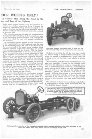
The chassis, as illustrated by us, has been built to take a private carriage bedy, but the inventor attaches more importance to his design for load-carrying work. The two rear axles are connected with each other so that they swing relatively to each other only in those planes which are perpendicular to the longi tudinal axis of the frame. This action is clearly shown in one of our photographs, which shows the wheel on the near side of the forward rear axle lifted up in its passage • over a road obstruction. Crosswise twisting of the axles is definitely prevented by two sets of tie rods, which connect the extremities of each axle to the sleeves embracing the propeller connecting shaft from the forward rear axle to the after rear axle. The photograph taken from the rear of the vehicle shows the off-side rear wheel passing over an obstruction and lifting the rearmost axle, causing it to rotate to a limited extent about its centre, thus showing very clearly the independent vertical but parallel movement of the two rear axles.
The two axles support their load upon a. fair of in verted, full-elliptical springs, the upper half of each spring being shackled at both ends to the side member of the frame, and the lower half of the spring (the leaves of which, however, being considerably shorter than the leaves of the upper half, convert this lower half into a supplementary spring) being attached to spring pins on the axle casings. The two halves of each spring are pivotally connected at the middle.
The power is taken from the four-cylindered engine through a gearbox which gives three forward speeds and a reverse, and thence by a propeller shaft to the differential on the forward front axle. The pro peller shaft passes through what the inventor describes as a hollow supporting lever (T-shaped by means of substantial webs), which is hinged at its ends in bearings on the side frame members, and at its rear end has a substantial universal joint enclosed in a torque ball.
The inventor says that he takes his propeller shaft through the differential box of the forward rear axle to the differential of the rearmost axle, through the sleeves, to which the stay rods already referred to are attached.
An extremely curious feature of the construction is the supporting lever, which extends from the rear of the rearmost axle to the ends of the brackets at the rearmost end of the frame, these brackets being stiffened laterally by tie-rods hinged to a pin on the rear cross-member of the frame. This is clearly shown in our photograph of the rear of the vehicle. This rear supporting lever is made telescopic so that it can expand and contract in order to follow the differential box on the rearmost axle in all its movements, a ball joint being interposed at its point of connection with the rear axle. As it can expand and contract, it obviously cannot transmit the driving power either when the vehicle is travelling forward or reversing, its chief function, therefore, being to fix definitely the position of the back axle in relation to the frame, preventing lateral movement of the rear axle and taking up all lateral stresses between the chassis and the wheels.
The construction of the front axle is again original and curious. Bolted to the centre of the semi-elliptical springs at the forward end of the frame is a shallow V cross-member, about the centre of which is pivoted the split front axle. The purpose of this arrangement is shown in the front view of the vehicle, which has been taken with the off-side front wheel passing over a 9 in. obstruction in the road. Braked are provided for all the four rear wheels, the brakes being so compensated relatively to each other, by means of compensating levers, that the braking power On the four rear wheels is always equal.
We mentioned that the wheels on the forward rear axle are steerable. Pivoted to the steering drop arm (near its fulcrum, in order to reduce the leverage), is a connecting rod, which has a universal joint about midway in its length, and this is connected at its rear end to a steering arm by which, an the Ackerman system, the forward rear wheels are turned. Without this turning of the foremost rear wheels in sympathy with the wheels on the steering front axle of the vehicle, abrasion of the tyres on the wheels of the foremast rear axle would inevitably occur.
The interests of the inventor are being looked after in this tountry by Messrs. Fred. Burris and Sons, of 7-11, Redcliffe Street, Bristol.