


Semi-automatic Gear-change Control
Page 68
If you've noticed an error in this article please click here to report it so we can fix it.
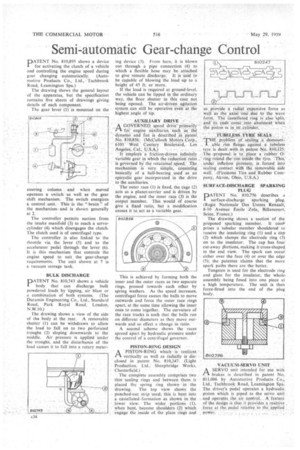
DATENT No. 810,895 shows a device
for activating the clutch of a vehicle and controlling the engine speed during gear changing automatically. (Automotive Products Co., Ltd., ..Tachbrook Road, Leamington Spa.) The drawing shows the general layout of the apparatus, but the specificatIon contains five sheets of drawitigt giving details of each component.
The gearlever (1) is mounted on the steering column : and when moved operates a switch as well as the gear. shift Mechanism. The switch energizes
a control .unit. the." brain-"' of the mechanismand it shoWn 'generally at 2. • The controller permits suction from the intake manifold (3) to reach a servocylinder (4) which disengages the clutch. The clutch used is of centrifugal type.
The controller is also linked to the throttle via the lever (5) and to the accelerator" pedal through the lever (6), it is this mechanism that controls the engine speed to suit the gear-change requirements. The unit shown at 7 is a vacuum 'storage tank.
BULK DISCHARGE
PATENT No. 840,743 shows a vehicle body that can discharge bulk powdered loads. by tipping, air blast or a combination of both systems. (The Duramin Engineering Co., Ltd., Standard Road, Park . Royal Road, London,
N.W.10.)
The drawing shows a view of the side of tha body at the rear. A removable shutter(I) can be withdrawn . to allow the load to fall on to two perforated troughs (2) sloping' downwards to the middle: Air pressure is applied -under "the troughs, and the distUrbance of the load causes it to fall into a rotary meter-. ing device (3). From here, it is blown out through a pipe connection (4) to . which a flexible hose may he attached to give remote discharge: It is said to be capable of blowing the load tip to a height of 45 ft. or more.
If the load is required at ground-level, the vehicle can be tipped in the ordinary way, the floor shutter in 'this case not being opened. The air-driven agitation system can still be operative even at the highest angle of tip.
• AUXILIARY DRIVE A GOVERNED, speed drive' primarily "" lot'. engine auxiliaries, such as the 'dynamo -arid 'fan is described in patent NO...816,856: (McCulloch Motors Corp
6101 ' 'West Century Boulevard, Los
;Angeles, ,Cal., USA.)' : It einplosiS 'a friction driven infinitely
• Variable" gear in Which the reduction ratio is governed by the rotational speed. The mechanism is very iirnPle, Consisting` ' basically of a ball bearing used as an epicyclic gear incorporated in the drive to the auxiliaries.
The outer race (1) is fixed, the cage (2) acts as a planet-carrier and is driven by the engine,' and the inner race (3) is the output member: This would Of course give a fixed ratiO, but a modification causes it to act as a Variable gear.
This is achieved by forming both the inner and the outer races as two separate rings, pressed towards each other by spring washers. As the speed increases, centrifugal force causes the balls to move outwards and force the outer race rings apart, at the same time allowing the inner ones to come together. The curvature of the race tracks is such that the balls run on different diameters as they move outwards and so effect a change in ratio."
A second scheme shows the races spread apart by hydraulic .piresstire under the control of a centrifugal governor.
• PISTON-RING DESIGN A PISTON RING Which is resilient -M. vertically as well as radially is disclosed in patent No. 810,247. (Light Production, Ltd.: Sheepbridge Works, Chesterfield) • The complete assembly comprises two • thin sealing rings and• between them is placed the spring ring -shown in the • drawing. The top view shows the punched-out strip used; this is bent into a castellated•formation as shown in the lower view. The wider portion's (I), when bent, 'become shoulders (2) which engage the .inside of the plain rings and so. provide a radial expansive force as well as the "axial one .due to the wave •. • forM.. The Castellated ring' is also 'split; and its ends come into abutment When the piston Is in AS cylinder:
. . SEALS !THE problem of sealing a, demount-1 able .. rim flange. against a" tubeless
tyre is dealtwith in patent No..810,125:
_ ,
The :proposal is to place a rubber 0,-. ring round the rim inside the tyre This • under, inflation presSure, is , forced into sealing contact with the removable Side wall. (Firestone Tire and Rubber Company, Akron, Ohio, U.SA.)
SURFACE-DISCHARGE SPARKING PLUG
DATENT No. 810,756 describes a I surface-discharge sparking ping. (Regie Nationale Des Lisines Renault; 8:10 Avenue Emile ZoJa, J3illancoprt, Seine, France.) The drawing shows a section of the proposed sparking member: It con-0 prises a -tubular member shouldered to receive the insulating ring (1) and a dap (2) which clamps the electrode ring (3) on to the insulator. The cap has four cut-away 'Tanjong, making it cross-shaped in the end view. The spark can occur either over the face (4) or over the edge (5); the" patentee claims that the more spark paths there are the better.
Tungsten is used for the electrode ring and glass for the insulator, the whole. assembly being fused into one piece at a high temperature. The unit is then force-fitted into the end of the plug body. •