


Patents Completed.
Page 30
If you've noticed an error in this article please click here to report it so we can fix it.
Complete specifications of the following patents will be sent to any address in the United Kingdom by the Sales Branch, Patent Office, Holborn, Voi.C., upon receipt of eightpence per copy.
A Slipping Differential.
F. B. Vane, No. 8581, dated 11th April, 1912.—The accompanying drawing shows a sectional plan of the driving gear of a rear axle. The road wheels
are each carried on a sleeve on the axle, and on the inner end of each sleeve is keyed a double male clutch-member. On the axle between the sleeves there is mounted a double female clutch-member driven by a belt or gearing from the engine. The two male members can be engaged with this other member so that the drive is transmitted from it to each of the road wheels. Preferably a metalto-metal clutch is used, so that the necessary slip to allow for differential action can take place easily. Within the housing of this gear there are fixed two female clutch-members with which the male clutch members on the sleeves can be engaged, so as to give a strong braking effect on each of the road wheels independently. Preferably a pedal control is used to operate the clutches by the levers shown in the drawing.
A Resilient Tire.
F. Lamplough and W. F. L. F. Lowndes, No. 13,266, dated 5th June, 1912.—A solid rubber tire of the usual tough character is made more resilient by cutting triamplar holes transversely through it, leaving inclined walls connecting the inner and outer parts of the tire. The spaces thus obtained are filled with soft elastic material, something like stranded rubber, and the whole is vulcanized. This tire is by choice mounted on a steel rim, and the soft cores are preferably made of pure sheet rubber stretched and tightly rolled before being cut off into lengths equal to the thickness of the tire. The sides of the core may be protected by tougher material if desired.
An Electric Self-starter.
C. F. Kettering, No. 28,903, dated under International Convention, 17th April, 1911.—In the arrangement described in the specification, a dynamoelectrie machine is used as a motor to drive the engine when starting up. It is also used as a generator to charge the accumulators when the engine is running. The special feature of this arrangement is, that a speed reducing gear is used when the electric machine is running as a motor, so that it can run at a high speed and drive the engine round for starting at. a low speed. Once the engine is running, this reducing gear is disengaged and the electric machine is run as a generator at a suitable speed.
The cells of the battery are coupled in series, so that a high voltage is obtained to drive the motor when starting. The motor has both series and shunt field windings which are differentially wound. The series winding alone is used for starting up, so that a powerful starting torque is obtained. Once the engine is running, the connecting mechanical gear is changed, so that the electric machine runs at a lower speed which is generally equal to the engine speed. To enable the accumulator to be charged at this speed the cells are arranged in parallel, or in groups in parallel. The lighting and ignition circuits are conveniently taken off one group, and they are always in operation whatever may be the other arrangements of the gear. The mechanical change-speed gear and the electric controller are interconnected, so that all the necessary changes are made at one operation.
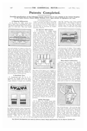
Roller Bearings.
R. F. Hall, No. 14,171, dated 18th June, 1912.—The accompanying illustration shows a roller bearing suitable for dealing with side thrust in addition to radial loads. Much difficulty arises in bearings of this type by the fact that they have to be bored from each end to provide shoulders in the middle for the thrust block, and this involves the risk of the boring at each end being eccentric, due to the resetting in the machine. This risk is obviated by doing all the boring from the right-hand end, leav ing a small shoulder at the left to pre vent the hearing rings' being pushed right through. The bearing is then assembled by inserting, first, a dust-excluding rin, and then the first roller bearing, which, in this case, is provided with three Bete, of milers. Then a skeleton thrust frame with two sets of balls is inserted. Between the balls are distance blocks faced on each side with hardened steel rings to take end thrust. A second roller bearing is then inserted and fixed in place by a ring screwed into the end of the hub shell and locked in any convenient manner.
Disc-clutch Lubrication.
Panhard and Levassor, No. 26,137, dated under International Convention, 12th January, 1912.e-The accompanying illustration shows a section of a disc clutch in which a disc is compressed between two rims forced towards one another by a number of springs arranged round the circumference of the flywheel. The clutch is thrown Out of gear by levers operated by a central sleeve, to compress the springs. In this type of clutch the lubrication is somewhat important as, if it is insufficient, the clutch is fierce, while if it is excessive, the disengagement of the clutch is not certain. A circular collar is fixed on to the right-hand
side of the flywheel. Oil is fed into this collar from a small tank formed on the right-hand end of the casing. From the collar, within which the oil is maintained by the centrifugal action, it is fed by small pipes—one of which is shown in section—on to the friction surface, so as to maintain a uniform state of lubrication.