 1
1 2
2 3
3 4
4 5
5 6
6 7
7 8
8 9
9 10
10 11
11 12
12 13
13 14
14 15
15 16
16 17
17 18
18 19
19 20
20 21
21 22
22 23
23 24
24 25
25 26
26 27
27 28
28 29
29 30
30 31
31 32
32 33
33 34
34 35
35 36
36 37
37 38
38 39
39 40
40 41
41 42
42 43
43 44
44 45
45 46
46 47
47 48
48 49
49 50
50 51
51 52
52 53
53 54
54 55
55 56
56 57
57 58
58 59
59 60
60 61
61 62
62 63
63 64
64 65
65 66
66 67
67 68
68 69
69 70
70 71
71 72
72 73
73 74
74 75
75 76
76 77
77 78
78 79
79 80
80 81
81 82
82 83
83 84
84 85
85 86
86 87
87 88
88 89
89 90
90 91
91 92
92 93
93 94
94 95
95 96
96 97
97 98
98 99
99 100
100 101
101 102
102 103
103 104
104 105
105 106
106 107
107 108
108 109
109 110
110 111
111 112
112 113
113 114
114 115
115 116
116 117
117 118
118 119
119 120
120 121
121 122
122 123
123 124
124 125
125 126
126 127
127 128
128 129
129 130
130 131
131 132
132 133
133 134
134 135
135 136
136 137
137 138
138 139
139 140
140 141
141 142
142 143
143 144
144 145
145 146
146 147
147 148
148 149
149 150
150 151
151 152
152 153
153 154
154 155
155 156
156 157
157 158
158 159
159 160
160 161
161 162
162 163
163 164
164 165
165 166
166 167
167 168
168 169
169 170
170 171
171 172
172 A SIX-WHEELER FOR LARGE-CAPACITY BUSES.
Page 84
If you've noticed an error in this article please click here to report it so we can fix it.
Details of a New Karrier WL6/2 Model Chassis Designed for Doubledeck Buses Accommodating 64 Passengers.
WE learn with interest that Karrier -Motors, Ltd., Karrier Works, Huddersfield, a company which has done so much towards the •development and popularizing of the rigid-frame sixwheeled vehicle, has recently designed a chassis specifically for double-deck
bodies accommodating 64 passengers. The new model closely resembles the WI,6, which, however, was intended for single-deck bodies only.
The main modifications and improvements which _had been effected consist of the use of' a much stronger frame, the fitting of more powerful pneumatically operated brakes, a petrol tank of larger capacity and pneumatics of larger section, More important still, however, are the alterations in the roar semibogie. To begin with, the springs are inverted twins in lieu of the single inverted semi-elliptic type previously employed. In view of the success which had been achieved in what may be termed the W.D. pattern six-wheeler, in 'which the driving and braking torque is taken direct to the frame, thus obviating any tendency for the semi-bogie to tip and to throw more of the drive on to one axle than on to the other, it is of great interest to find that this method of transmitting the torque is incorporated in the new Karrier. Two stout tubes are mounted across the frame and the torque from the respective driving axles is taken to these.
We will now give a brief specification of the WL6/2 model.
The main dimensions are, overall length, 28 ft. ; overall width, 7 ft. 44 ins.; dash to end of frame, 22 ft. 9 ins.; ground clearance up to 14 ft. 6 ins., from dumb irons, 10i ins. ; rear axle clearance, ei ins.; chassis weight, 3 tons 19 cwt.; gross load, 6 tons 10 cwt.; wheelbase, 17 ft. 6 ins. ; track, 6 ft. 4 ins.; turning circle, 60 ft.
The power unit is a six-cylindered monobloc, with detachable heads, having a bore of 100 min. and a stroke of 140 mm. It develops 50 b.h.p. at the normal speed of 1,250 r.p.m. and gives a maximum b.h.p. of 80. This unit is supported in a sub-frame having threepoint suspension.
Both the crankshaft and the camshaft are of nickel steel and tlie crankshaft has four bearings. Nickel-steel is also employed for the valves, which are arranged side by side. The ignition is
D14
effected by a h.t. magneto with a vernier adjustment. It is driven from the timing case by an enclosed chain. To avoid any trouble with carburation, two Zenith instruments of the vertical type are provided.
A large oil pump in the sump is driven by spiral gears from the camshaft and forces oil to each main and big-end bearing. Oil from an adjustable relief valve lubricates the timing wheel and magneto driving chain.
The clutch is an adjustable-cone pattern faced with fabric, a stop facilitating gear-changing.
The casing of the gearbox is of castiron. It is mounted at three points on tubular cross-members, and both the mainshaft and layshaft have three bearings. The gears themselves are of nickel-chrome steel and provide four forward speeds and a reverse, the lastnamed remaining idle when not required. An important point is that the gearboi can easily be lowered and withdrawn from beneath the chassis. The gear ratios and corresponding speeds, with the engine running at 1,250 r.p.m., are top, 8.66 to 1, 15.45 m.p.h.; third, 14.42
to 1, 9.3 m.p.h. ; second, 25 to 1, 5.35 m.p.h. ; first, 39.82 to 1, 3.35 m.p.h. ; reverse, 54.4 to 1, 2.48 m.p.h.
Operation of the change-speed mechanism is through a right-hand gate, the gears being positively locked by spring-loaded plungers. From the gearbox the drive is taken first through a short_shaft with fabric discs to a transmission-brake drum, and thence by a tubular propeller shaft and two startype roller-bearing universal joints to the first driving axle. A splined plunger joint protected by a sliding muff is, of course, incorporated.
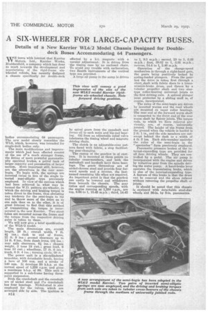
The axles of the semi-bogie are driven by inverted worms and the road wheels are mounted on taper roller bearings. The rear end of the forward worm shaft is connected to the front end of the rear worm shaft by Spicer joints. The torque• rods, to which we have referred previously, are, of course, universally jointed. The height of the frame from the ground when the vehicle is loaded is 2 ft. 1 in., and the side members are outswept behind the dash to a width of 4 ft. 3 ins. Each side-member encircles the axles of the semi-bogie in the "spectacles" form previously employed.
Pneumatic pressure brakes of the internal-expanding type are provided for all four driving wheels. They are controlled by a pedal. The air pump is incorporated with the engine and driven by reduction gear from the spindle driving the water pump. A hand-brake lever operates the transmission brake, which is also of the internal-expanding type. A feature of this brake is that the drum can be removed and the shoes refaced without removing the propeller shaft or joints.
It should be noted that this chassis Is equipped with detachable steel-disc wheels and 36-in. by 8-in. pneumatics.