


Now a French Rotary Engine
Page 64
If you've noticed an error in this article please click here to report it so we can fix it.
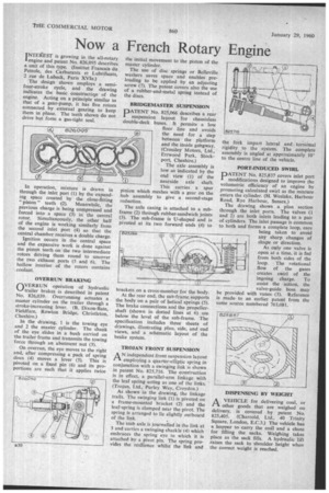
INTEttEST is growing in the all-rotary 'engine and patent No. 826,095 describes a unit of this type. (Institut Francais du Petrole, des Carburants et Lubrifiants, 2 rue de Lubeck, Paris XVIe.) The design shown employs .a semifour-stroke cycle, and the drawing indicates the basic constructiqn of the engine. Acting on a principle similar to that of a gear-pump, it has five rotors connected by external gearing to keep them in phase. The teeth shown do not drive but form a gas-tight seal.
In operation, mixture is drawn in through the inlet port (1) by the expanding space created by the close-fitting " piston " teeth (2). Meanwhile, the previous charge is being compressed and forced into a space (3) in the central rotor. Simultaneously, the other half of the engine is working similarly from the second inlet port (4) so that the central chamber receives a double charge.
Ignition occurs in the central space and the expansive work is done against the piston teeth on the two intermediate rotors driving them round to uncover the two exhaust ports (5 and 6). The hollow interior of the rotors contains • coolant. OVERRUN BRAKING
OVERRUN operation of hydraulic trailer brakes is described in patent No. 826,039. Overrunning actuates a master cylinder on the trailer through a stroke-increasing lever. (B. Dixon-Bate, Fieldfare, Rowton Bridge, Christleton, Cheshire.) In the drawing, 1 is the towing. eye and 2 the master cylinder. The shank of the eye slides in a bush carried on the trailer frame and transmits the towing force through an abutment nut (3).
On overrun, the eye moves to the right and, after compressing a pack of spring discs (4) moves a lever (5). This is pivoted on a fixed pin (6) and its proportions are such that it applies twice
the initial movement to the piston of the master cylinder.
The use of disc springs or Belleville washers saves space and enables preloading to be applied by an adjusting screw (7). The patent covers also the use of a rubber-and-metal spring instead of the discs.
BRIDGEMASTER SUSPENSION
DATENT No. 825,066 describes a rear suspension layout for chassisless double-deck buses. It permits a low floor line and avoids the need for a step between the platform and the inside gangway. (Crossley Motors, Ltd., Errwood Park, Stockport, Cheshire.)
The axle assembly is low as indicated by the end view (1) of the nearside axle shaft. This carries a spur pinion which meshes with a gear on the hub assembly to give a second-stage reduction.
The axle casing is attached to a subframe (2) through rubber-sandwich joints (3). The sub-frame is U-shaped and is pivoted at its two forward ends (4) to brackets on a cross-member for the body.
At the rear end, the sub-frame supports the body on a pair of helical springs (5). The brake connections and the propellershaft (shown in dotted lines at 6) are below the level of the sub-frame. The specification includes three sheets of drawings, illustrating plan, side, and end views, and a schematic layout of the brake system.
TROJAN FRONT SUSPENSION
AN independent front suspension layout employing a quarter-elliptic spring in conjunction with a swinging link is shown in patent No. 825,716. The construction is in effect, a parallel-arm linkage with the leaf spring acting as one of the links. (Trojan, Ltd., Purley Way, Croydon.)
As shown in the drawing, the linkage trails. The swinging link (1) is pivoted on a frame-mounted bracket (2) and the leaf-spring is clamped near the pivot. The spring is arranged to lie slightly outboard of the link.
The stub axle is journalled in the link at 3 and carries a swinging shackle (4) which embraces the spring eye to which it is attached by a pivot pin. The spring provides the resilience whilst the link and
the fork impart lateral and torsional rigidity to the system. The complete assembly is angled at approximately 10° to the centre line of the vehicle.
PORT-INDUCED SWIRL
PATENT No. 825,837 covers inlet port modifications designed to improve the volumetric efficiency of an engine by promoting calculated swirl as the mixture enters the cylinder. (H. Weslake, Harbour Road, Rye Harbour, Sussex.)
The drawing shows a plan section through the inlet ports. The valves (1 and 2) are both inlets leading to a pair of cylinders. The inlet passage is common to both and forms a complete loop, care being taken to avoid any sharp changes of shape or direction.
As only one valve is open at a time, it is fed from both sides of the loop. The rotational flow of the gases creates swirl of the ingoing charge. To assist the action, the valve-guide boss may be provided with vanes (3). Reference is madeto an earlier patent from the same source numbered 763,081.
A VEHICLE for delivering coal, or 1-1 other goods that are weighed on delivery, is covered by patent No. 825,405. (Charrold, Ltd., 40 Trinity Square, London, E.C.3.) The vehicle has a hopper to carry the coal and a chute for filling the sacks. Weighing takes place as the sack fills. A hydraulic lift raises the sack to shoulder height when the correct weight is reached.