


A Simple Form of Self-adjusting Tappet
Page 56
If you've noticed an error in this article please click here to report it so we can fix it.
A SELF-ADJUSTING tappet of IA exceptional simplicity forms the subject of patent No. 662,501, which comes from W. Scott, "Treetops," Birmingham Road, Shenstone, Staffs.
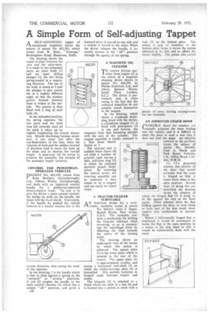
The drawing shows the tappet in place between the cam and the valve-stem. It is made in two telescopic parts, an outer body (1) and an inner sliding plunger (2), the two being spring-loaded in a separating direction. The top of the body is coned at 3 and the plunger is also coned, but at a slightly different angle, so that the annular groove formed between them is widest at the outside. The groove i then filled with a ring of steel bails (4).
In the unloaded position, the spring separate.> the two parts and the balls then fall inwardly until all the slack is taken up by slightly lengthening the overall dimension. Should shortening become necessary, it can occur just after the top-dead-centre of the cam, when the removal of load and the sudden reversal of direction tend to move the balls up the slope and so shorten the overall length. A spun-over lid (5) serves to preserve the assembly, but permits of the necessary length variation.
CONTROL , FOR PEDESTRIANOPERATED VEHICLES
P ATENT No. 662,439, comes from I Rose Brothers (Gaiosborough), Ltd., Albion Works, Gainsborough, and deals with an improved control handle for a pedestrian-Operated battery-electric truck. The aim is to give the driver a more natural control; the harder he pulls on the handle, the faster will the trvek travel. Conversely, if the handle be pushed the vehicle behaves in a similar manner but in the
reverse direction, thus easing the work of the operator.
In the drawing, 1 is the handle which is free to slide against a spring in the " forward" or " reverse " positions. A rod (2) couples the handle to the main control rheostat (3) which has a central " off " position, and gives a
A38
forward drive if moved to one side and a reverse if moved to the other. When the driver releases the handle, it instantly returns to the " off " position through the agency of the spring.
A MAGNETIC OIL CLEANER
TO remove ferrous partides from engine oil is the object of a magnetic cleaning device shown in patent NO. 664,599, by Philips Electrical, Ltd., and others, Spencer House, South Place, London, E.C.2. The device is particularly easy to clean owing to the fact that the collected impurities do not actually attach themselves to the magnet.
In the drawing, which shows a crankcase drainplug fitted with the device, a cylindrical magnet (1) is fitted with pole-pieces (2) at top and bottom, the magnetic lines thus becoming parallel with the axis of the cylinder. The magnet assembly is totally enclosed in a thin • brass sheath shown at 3.
• The external unit is another brass sleeve (4) cut with a number of grooves, each having a split, soft-iron ring (5) to which the collected particles attach themselves. By removing the central screw, the iron-ring assembly can be removed; it then ceases to be a magnet and can easily be wiped clean.
A TRACTOR-TRAILER TURNTABLE
PA
A N American design for a semi
• trailer, turntable comes in patent No. 664,611, from J. Apgar, Bound Brook, New Jersey, U.S.A. The turntable contains a Mechanism for shifting the king-pin sideways when cornering, so as to compensate for centrifugal force by offsetting the toad towards the centre of the turning circle.
The drawing shows an underneath view of the means by which this action is achieved. The square plate (1) is the lower plate, which is secured to the rear of the tractor. The upper plate (2) is approximately circular, and carries a horizontal rock-shaft (3) on which the trailer-carrying plate (4) is journalled. This permits variation in vertical angle between tractor and trailer. .
The king-pin (5) is attached to • a block which can slide in a slot (6) and is formed into a pinion to mesh with a
rack (7) on the bottom plate. The action is easy to visualize; as the bottom plate turns, it moves the pinion sideways in its slot, and so offsets the trailer slightly.. The patent also covers
details of some locking arrangements for the turntable.
AN IMPROVED COACH DOOR rLOSABLE -doors for coaches are .--nisually adjacent the steps leading into the vehicle, and it is difficult to place the door in such a way that it does not foul the steps. An effective solution to the problem forms the subject of patent No. 664.862, from A. Needs and Park Royal Vehicles, Ltd., Abbey Road, London, N.W.I0.
In the e proposed scheme, that portion of the door r' that would normally fold the steps' is hinged so .:that it clears them when in the Open position. Several ways of doing this are described' the drawing
. shows the simplest in which the hinged flap (1) is madeto lie flat against the step as the °door opens. Other schemes show the flap folding against the door, or even rising' to form part of the step tread; these require. cam mechanisms to operate
them. "•
Where "it' hOrizontally hinged flap is employed, it would be convenient to house the flap in the open position in a recess in the step tread so that it would be substantially flush with the tread.