


A NEW RUBURY SELF-ASSISTED BRAKE.
Page 30
If you've noticed an error in this article please click here to report it so we can fix it.
A Resume of Recently Published Patent Specifications.
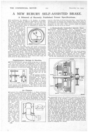
IN specification No. 243,052, J. M. Rubury, of London, W., shows a number of different applications of the floating fulcrum type of self-assisted brake. We use this term so as to distinguish this class of brake from the servo type, in which some outside power is employed to operate the brake. In the present case, we have selected one of the methods of application shown, as we consider it the most useful of the various examples. As described, the brake should act as a self-assisted brake more when the drum is revolving in the direction of the arrow as, when revolving in the apposite direction, the drag of the -drum on the leading and following shoes would result in a great pressure on the
longer flat on the expanding cam, and would consequently resist its rotary movement. The floating shoes are controlled by means of the link,s which are pivotally 'anchored at (A).
An adjustment is provided between the leading and following shoes, as shown. One of the difficulties designers have to meet with in the arrangement of such brakes is the necessarily large diameter of the wheel boss when ball or roller hearings are employed, which leaves little roam for such pivots as those shown at .(A).
Supplementary Springs in Shackles.
SUPPLEMENTARY springs which do the duty of shackles are by 110 means new, as 'experiments in this direction were made many years ago, and with, such good results that we wonder more attention has not been given to improving the suspension of safid-tyred vehicles by means of some such device. If we remember rightly, the frequent breakage of springs used for the purpose was one of the snags.
In the present specification, No. 243,170, by P. D. Armstrong, of Sydney, Australia, however, this is guarded against to an extent, as, should the springs break, there is the loop formed by the plates which would prevent total disablement. We think we have seen better applications of the spring shackle, however, than those described in this 'patent.
IN patents Nos. 243,282 and 237,895, A. A. Bull, of Detroit,
U.S.A., describes two forms of air cleaner. The arrangement shown is typical af the various forms described in the specification, as 'a stationary vane, shown on the right, sets the air swirling round the wall of the chamber so that the heavy, particles of dust are thrown downwards, and escape through the ports (A), whilst the cleansed air passes through the central tube to the carburetter. Apart from the particuhir form here described, it is curious that some form of air cleaner has found so little favour in this country. It may be said that our roads are more dust free than those of other co-mules, but that a u s t, 245282
even in a fine form, is found none can deny. Apart from the Wearing away of pistons and cylinders due to dust, there is the formation of sorealled carbon which is known to be mainly composed ot road. dust. This' nuisance could be largely avoided by the use of an air cleaner.
A Hydraulically Controlled Epicylic Gear.
WILLIAM REARDMORE (Lord Invernairn) and A. E. L. Chorlton, in specification No. 236,545, show a method of controlling epicyclic gears suitable for the transmission of high powers by mean of hydraulic pressure.
It will be seen from the sectional view that the shaft on the left is the driver, whilst that on the right is the driven. Attached to the driver is a sun-wheel, whilst attached to the driven is the spider which carries the pinions which engage in the sun-wheel and also in the annulus which goes to complete the still and planet gear. Attached also to the driven shaft is the large disc which forins the direct drive. The casing is non-revolving and carries with it the brake which holds against rotation the annulus whilst the low gear is in operation. Plate clutches are provided for arresting the annulus against rotation, also for coupling the parts connected with the drive shaft and the driven shafts while high, or direct, gear is in operation.
These plate clutches are arranged in the usual manner, viz., each alternate plate engages the outer member and each other alternate plate engages the inner member, although the drawing does not show this necessary detail.
So far the construction -is of ordinary design, the invem tion apparently lying in the method of operating the clutches.
Behind each of the clutches a number of plungers is arranged around the circle, all of which are operated by Means of fluid forced through passages as shown. Springs are provided to effect the release of the plungers. Special valves are shown which direct the fluid to the clutch which it is desired to put into operation. In the example shown, the left-hand clutch arrests the annulus for the low gear, whilst the right-hand clutch operates the high gear. In the body. of the specification mention is made of the clutches being able to permit such slipping as is necessary to enable the drive to continue, so that the clutches, by means of slipping, will bridge the gaps between the various steps in the gear. We have considerable doubt as to the accuracy of this, as experience has shown that when going from a high gear to a low one any slippage may be relied upon to keep up a certain amount of torque, equal to that of the high gear, but it -will not enable the torque gradually to rise if the low gear be brought into action slowly through wasting power in slipping of a clutch.