


Patents Completed.
Page 18
If you've noticed an error in this article please click here to report it so we can fix it.
Complete specifications of the following patents will be sent to any address in the United Kingdom upon receipt of eightpence per copy at the Sale Branch, Patent Office, Holborn,
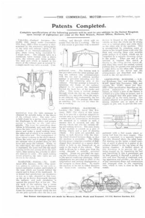
VAL V ES.—Panhard Leva_ssor.—No. 14,278, 1910, dated under Convention 17th June, 1909.—This invention is characterized by the concentric arrangement of the inlet and exhaust valves of the cylinder of an internal-combustion engine, these valves being controlled by a single lever. The exhaust valve is a mushroom valve formed with a sleeve stern, the eshaust port being annular. The inlet port which is formed in the sleeve of the exhaust port is covered by a simple mushroom valve on a rod. Corn.
munication from the inlet passages is obtained by suitable holes in the sleeve of the exhaust valve. The inlet valve is held closed by a spring which rests on the diaphragm in the sleeve and presses agaiust a cross-har on the inlet valve spindle. The lever for controlling these valves is bifurcated, and each arm rests above the inlet cover of the exhaust-valve sleeve and under a small rocking lever, the other end of which is in contact with the inlet-vaive rod. 'The arrangement of these valves is shown in the above sketch. When the outer end is pressed upwards, the exhaust valve is pressed down by this lever and opens the exhaust. When, on the other hand, the outer end of the lever is depressed, the inner end lifts the small rocking levers and presses down the inlet valve, thus opening the cylinder to allow the mixture to enter. The small rocking levers actuating the inlet valve are not shnwn in the sketch.
RA DIATOR.—Sidd elev.—No. 2,107, dated 27th January, 1910.—This invention relates to radiators for MP with he ternal-combustion engines, particularly of the type which are located behind the engine and in front of the dashboard. It is stated that satisfactory air circulation is not, as a rule, obtained in this type. as the air is drawn downwards through the radiator, and such circulation is against the natural flow of hot air. The top tank of the radiator has a recess formed in its rear face that is between the tank and the dashboard. This recess forms the passage through which the hot air can pass upwards when the fan is not
working, and through which cold air passes when the fan is working. The top of this recess is provided with a suitable perforated rover. The bottom tank is also provided with the usual passage putting the radiator into communication with the inn and in addition another passage is provided extending over the whole of the remaining area of the radiator. This last passage is formed by extending the frame of the radiator adapted to lie against the dashboard beyond the back face of the tanks and tubes. This forms a vertical passage through which the hot air can circulate naturally, i.e., upwards, when the engine is not running and consequently the fan is not working. The passage also forms an auxiliary inlet for cold air when the fan is working.
AGRICULTURAL MACHINES. — Landrin.—No. 4,201, dated 19th February, 1910.--The object of this invention is to provide a machine adapted for various uses in agricultural work wherein a motor and its transmission mechanism are mounted in a vehicle in such a manner that it operates not only the driving wheels but also the various tilling and cutting devices. The main frame of the machine is carried on a pair of driving wheels and a pair of steering
wheels. Two seats are provided, one facing in each direction with the steering wheel situated between them, so that
the machine is reversible. The tilling devices proper comprise a number of dishshaped discs mounted on a square shaft, which is held in the framework at an angle to the track of the vehicle. This shaft is driven by a chain gear from the motor through a suitable universal coupling Means are provided for varying the inclination of the shaft according to the special conditions obtaining. Other adjustments are provided to allow of the longitudinal and vertical displacement of the scrapers on these discs. To enable the machine to be run in either direction the frame-work carrying the tilling
devices is hinged at the middle of the vehicle, so that, the whole can be swung over in a vertical plane and come down on the other side of the machine. This is accomplished by attaching ropes or chains to the hinged frame-work near the discs and carrying these over suitable guide pulleys to a winch, which can be connected by a suitable reversing clutch to the motor. When one end of the traverse is reached this clutch is hrown in, the tilling devices wound off, and when they reach the central vertical position they are passed over and allowed to come down on the other side. Various modifications of the device and the arrangements are described and illue tutted in the full specification.
LIQUID-FUEL BURNERS. — S.M. Car Syndicate, Ltd., and Another.—No. 26,818, dated 18th November, 1909, and cognate No. 10,921, dated 3rd May, 1910.—This specification describes an improved construction of liquid-fuel buener, in which a part of the burner is utilized as a pilot lamp or burner, and it is so arranged that this pilot lamp uses the same oil as the main burner. The method adopted is to partition off in the mixing chamber one or more of the nipples or jets, and, to provide this corn
partment with a fuel nozzle which re. ceives fuel from the main supply. This fuel is vaporized in a separate vaporizing tube situated above the pilot lamp. For starting up the latter, a small quantity of spirit is placed in a glitter or de. pression formed in the top plate of the mixing chamber. A further object of this invention is to prevent the jets' being clogged up, by vaporizing the fuel and converting it into a permanent gas by first passing it through a red-hot retort and then through a combined cooling apparatus and purifier ; the latter is of any convenient shape and construction and arranged close to the vaporizing tube, which in turn is close to the fuel nozzle.