


Carburetters.
Page 11
Page 12
Page 13
If you've noticed an error in this article please click here to report it so we can fix it.
A Few of the Successful Types Now in Use on Commercial Vehicles.
The carburetter has always been one of the chief objects for the attention of inventors and designers of motorcar engines, and the records at the Patent Offices of this and other countries show how much mental labourmuch of it futile—has been expended on this component. Unfortunately, many carburetters are of such a complicated nature that only their inventors were ever convinced of the practicability of such productions. The problem which inventors have to face is not, by any means, an easy one ; a state of adjustment that would ensure the almostperfect running of an engine at low or moderate speeds might be absolutely useless for the same engine when running at higher speeds. Wide differences in engine speeds have the effect of upsetting the correct proportions of air to petrol vapour, and no arrangement of automatic or auxiliary-air valves will make the exact and necessary corrections for such disturbances.
The ideal carburetter would be one in which the proportion of air to petrol, once adjusted to suit the atmospheric conditions of the moment, should not be effected by variations in the suction speed of the mixture on its way into the cylinders. As the speed of an engine is increased, and, consequently, a greater quantity of gas per minute is needed in the cylinders, the cross-sectional area of the mixing pipe should be enlarged in direct proportion; in other words, the ideal mixing chamber should be capable of being expanded. The quantity of petrol admitted should also be increased at the same time as the augmented supply of air, but the fixed ratio of petrol to air should not be disturbed by the change. The manner in which representative motor manufacturers have endeavoured to meet these requirements are many and ingenious. Among the most-practical devices are Those fitted by Commercial Cars Ltd., whose carburetter is extremely simple in design and construction. The vertical-piston type, as adopted largely by Milncs-Daimler, Ltd_ is a farm of carburetter which gives equally-good results with petrol, benzol or alcohol, and the paraffin vaporizers, which are fitted by Jahn I. Thornycroft end Co., Ltd., whenever required, to lorries and tractors for military requirements or for service abroad, are also very practical in design and satisfactory in operation. N
ous proprietary carburetters may be obtained, and a few of the better-known ones are illustrated and described en ibis and the following two pages. To this list might w ell be added diagrams and descriptive matter relating to many other highly-successful carburetters, but lack of epee prevents their inclusion in the present article. We have selected for treatment but a few of the many devices which may now be obtained, and whieli devices are free from complicated working parts.
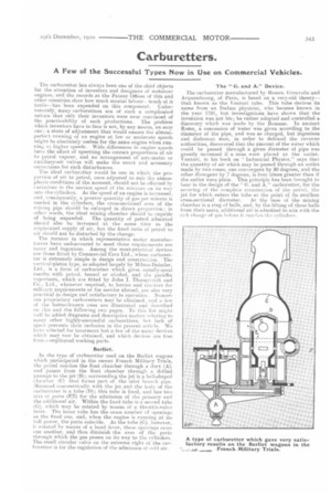
Berliet.
En the type of carburetter used on the Berliet wagons which participated in the recent French Military Trials, the petrol reaches the float chamber through a duct (A), and passes from the float chamber through a drilled passage to the jet (B); surrounding the jet is a bell-shaped (+amber (C) that forms part of the inlet 'branch pipe. Mounted concentrically with the jet and the body of the carburetter is a tube (D); this tube is fixed, and has two sets of ports (EE) for the admission of the primary and the additional air. Within the fixed tube is a second tube (G), Nvhich may be rotated by means of a throttle-valve lever. The inner tube has the same number of openings as the fixed one, and, when the engine is running at its full power, the ports coincide. As the tube (G), however, is rotated by means of a hand lever, these openings cross mine another, and thus diminish the area of the ports through which the gas passes on its way to the cylinders. The small circular valve on the extreme right of the carburetter is for the regulation of the admission of cold air.
The "G. and A." Device.
the carburetter manufactured by Messrs. Grouvelle and Arquembourg, of Paris, is based on a very-old theory— that known as the Venturi tube. This tube derives its name from an Italian physicist, who became known in the year 1791, but investigations have shown that the invention was not his; he rather adopted and controlled a discovery which was made by the Romans. In ancient Rome, a concession of water was given according to the diameter of the pipe, and was so charged, but ingenious and dishonest men, in order to defraud the revenue authorities, discovered that the amount of the water which could be passed through a given diameter of pipe was greatly increased if a cone were placed at the outlet. Venturi, in his book on " Industrial Physics," says that the quantity of air which may be passed through an outlet made by two cones, one convergent by 30 degrees, and the other divergent by 7 degrees, is four times greater than if the outlet were plain. This principle has been brought to bear in the design of the" G. and A." carburetter, for the securing of the complete atomization of the petrol, the jet for which enters the tube at the point of its smallest cross-sectional diameter. At the base of the mixing chamber is a ring of balls, and, by fhe lifting of these balls from their seats, additional air is admitted to mix with the rich charge of <,as before it. renclies the cylinders.
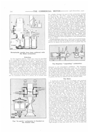
Polyrhoe.
In this ingenious device, which may truly be described as an expanding carburetter, the jets are formed by slots in a number of very-thin brass plates. These plates are punched and slotted ; they are then superimposed, clamped between two plain surfaces, and so arranged that the slots are " staggered "—that is to say, the slots on adjacent plates are not opposite to each other. Petrol is admitted through an opening in the top of a very-simple float chamber, and, passing through a felt filter, and along a thin passage to the punched holes in the jet plates, the spirit issues from the slots as a broad band of line spray.
The operation of the Polyrhoe carburetter is as follows : on the aspiration stroke of a piston, air is sucked into
the cylinder through the port of the carburetter marked on the drawing "Air inlet," and, during its passage, the air picks up the spray, or cascade, of petrol, which, by reason of the local reduction of pressure caused by the suction, is induced to flow from the slots in the jet plates —the normal level of the petrol being but slightly below the level of the lowest jet plate. As the engine is accelerated, and the demand for gas becomes greater, the increased suction causes a further fall of pressure in the mixing chamber and, incidentally, also in the space behind a suction-operated piston—the stem of which piston is hollow, and directly open to the mixing chamber. Any fall in the pressure between the suction-operated piston is followed by the atmosphere's forcing the piston outwards against the action of a light helical spring. When this movement of the piston takes place, the cascadetrol spray is widened in direct proportion to the increased area of the air inlet.
A hand-operated slide-valve, which may be moved transversely across the mouth of the air inlet, is also provided, and by its means the proportion of air to petrol may be adjusted to suit atmospheric conditions. The functions of this hand-operated slide-valve must not be confused with those of the suction-operated piston. Any movement of the latter alters both the lengh of the air-inlet slot and the width of the cascade of petrol, whilst any movement of the hand-operated slide-valve increases, or decreases, the width of the inlet slot, and alters the proportion of air to petrol, but has no control over the cascade width.
The Solex.
A duplex-jet carburetter of very-simple and practical form has recently been introduced by Messrs. Wolf and Co., of 138, Southwark Street, SE., and we hear from many quarters accounts of remarkable results achieved ‘vith this most-practical device. It will be seen that a normal form of float is employed, but the arrangement of the inlet valve (p) is unusual; its position is clearly shown in the sectional drawing. The main jet (G) is situated in the main choke chamber, and is, of course, surrounded by the choke tube (S). The auxiliary jet, the passage for which is indicated by the letter B, for convenience of construction, is made longer than the main one, and the jet hole (g) is correspondingly large on that account ; the float surrounds the auxiliary jet column, and on to this latter a combination clamping-device (E) is screwed. By an ingenious arrangement of channels in this screw and in the surrounding float-chamber cover (C), petrol from tile auxiliary jet is led upwards into a portion of the casing which holds the throttle valve. This latter valve is of special form ; twin vanes take the place of the usual single butterfly. The inner edge of this valve seats against the inside of the throttle casing, and it is at this position' that the petrol from the auxiliary jet enters the induction pipe, a small hole connecting the petrol channel to the space between the two vanes. The ball (R) is normally carried on a seat which is formed in a special lug that is part of the float-chamber-top casting (C); it controls the opening to a small channel which passes through the clamping screw (E), over the auxiliary jet orifice (g), and so up to the throttle. As soon as the stage of tension is high enough to keel) the relief ball valve off its seat the
auxiliary jet is put out of action, the main jet arid choke tube being then entirely responsible for the whole of the carburation.
Zenith.
Another well-known carburetter, and one by which good results have been achieved, is the Zenith, a sectional view of which we reproduce herewith. The two jets (G and 1-1) are arranged concentrically, both of them opening at S; the regular jet has a central opening, whilst the supplementary jet is of annular form. The annular jet (H) communicates through the passage F with a chamber (J), which is open to the atmosphere. Owing to the principle of its construction, the Zenith carburetter offers the following advantages: (1) it is absolutely automatic—that is to say, whatever may be the speed of the motor, it produces a mixture. that causes the engine to deliver its maximum power at that speed ; (2) all of the air drawn in serves to spray the petrol, and the mixture is therefore very homogeneous; (3) the device does not comprise a single moving part, and the vibrations due to road shocks, or to the intermittent suction of the motor, can, therefore, have no effect on it, and do not interfere with the carburation, as is the case with many so-called automatic
carburetters which have spring-returned supplementary-air valves; (4) operation at low speed is quite practicable, and the re-starting of the motor is greatly facilitated by the presence of the compensating nozzle and the auxiliary suction tube.
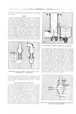
The Davis Paraffin Carburetter.
Several of the carburetters already named, if provided with hot-water jackets and suitable air valves, may be adapted for the use of paraffin or other heavy-oil fuel, but more-uniform results may be relied upon if a carburetter which is of special design for the use of such fuel be employed_ One of the most. successful of these devices is that made by the Davis Paraffin Carburetter Co., of Station Avenue, Kew Gardens, Surrey. A sectional illustration of one of the latest types produced by this company is shown herewith. In the Davis device, the delivery of the fuel, and its complete atomization are effected mechanically. The shaft (A) is driven by belt or otherwise from the camshaft or crankshaft, and, at the inner end of this shaft, there is a cam (13) which operates a small plunger (C). During the down stroke of this plunger, fuel is drawn in through the pipe (D), and, during the up stroke of the piston, it is delivered through the three way valve (E) and a small external pipe to the inlet (G). Air is sucked in through the branch (H), and, picking up the paraffin entering by the jet (G), it is mechanically mixed by the paddle wheel (J) which is driven at a high rate of speed from the shaft (A). Before passing the throttle valve (K) on its way to the cylinders, the mixture must pass through a water-jacketed pipe, in which are a number of (TOSS tubes (L), and through these tubes the hot water also circulates. If the carburetter is adjusted to run the engine at a definite speed, it will be seen that, so soon as that speed is exceeded, the governor weights (M) will fly outwards and cause the sleeve (N) to be moved axially along the shaft (A). This movement of the sleeve operates the throttle valve (K) through the medium of a lever and link ; the three-way valve (E) is also interconnected, so that, when the throttle valve is partly or entirely closed, some or all of the fuel delivered by the plunger (C) is returned to the fuel tank. A large number of these carburetters is in use, both for vehicles and stationary engines, and giving excellent results both as regards efficiency and certainty of action.