


Power-assisted Steering Mechanism
Page 58
If you've noticed an error in this article please click here to report it so we can fix it.
nillliATENT No. 797,703 shows a power' assisted steering mechanism, the chief novelty of which is the interposition of a torsionally elastic member between the steering wheel and the worm box. The lost motion permitted by this arrangement is used to control the hydraulic assistance. (Adolph Saurer, Ltd., Arbon, Switzerland.) The wheel when turned transmits rotation through a small diameter shaft (1). This acts as a torsion rod, causing the movement at the lower end to lag slightly. Assuming no power were available, the torque would ultimately turn the sleeve (2) and with it the worm (3).
Normally, however, the initial turning movement is converted into axial movement of the rod (4) by means of projections working in helical slots (5). The up-and-down movement so created operates the control valve (6) for the hydraulic pressure and causes the servo cylinder (7) to apply amplified force to the drop arm (8).
SPRING-ASSISTED HAND BRAKE
IQ RAKE application is divided into two
distinct phases; first the shoes must be brought to the drums, and then the braking force applied. The former is a light operation, requiring movement rather than force, but the latter demands considerable force. Many two-speed movements have been proposed to meet this requirement, and patent No. 797,002 shows a hand brake in which the first movement is provided by a spring, and a low-geared lever completes the operation. (Maschinenfabrik Augsburg Nfirnberg A.G., Ntirnberg, Germany.) The drawing shows a power-brake layout incorporating the scheme. A cylinder (1) contains a spring which can apply light operating movement to the handbrake cross-shaft (2). Normally, the spring is held compressed by air pressure and is non-effective.
When the hand brake lever (3) is pulled, it first opens a valve (4) which exhausts the air from the spring cylinder and allows the spring to move the brake into the ready position. The hand-lever ratchet system permits this movement to B24 occur and then, when the lever is pulled further, performs the actual braking.
The system is not dependent on the presence of air pressure for its functioning, but only on its absence. It is therefore safe from failure.
AN ENGINE STARTING DEVICE A HAND-OPERATED generator for
supplying current to a conventional starting motor forms the subject of patent No. 796,957. It is intended for use in adverse circumstances, such as arctic weather, or on a vehicle with a run-down battery, or it may even be used as the standard method of starting vehicles from a garage. (Simms Motor Units, Ltd., and E. Leyburn, Oak Lane, London, N.2.) A manually operated generator could not directly provide sufficient electrical energy to swing a stiff engine, hut in this case a flywheel is incorporated to form an energy reservoir. This can be accelerated manually over a period of time, and then used to drive the generator at a high output for a short time.
The drawing shows the construction of the proposed unit. The handle (1) drives, via a three-stage speed-increasing gear, the generator (2). The flywheel is an annular member (3) which surrounds t he generator, thus giving the maximum momentum for the minimum mass.
In use, the generator and its flywheel are raised to a high speed and then the starter switch is closed. The generator is a series, wound machine but is provided with a small shunt winding to enable the field to be built up during acceleration.
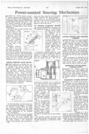
For starting a number of vehicles from their home garage, the generator could he kept running by a small-power mains motor. LIFTING DEVICE FOR STRADDL: CARRIER
VEHICLES used for transporting pipe: bars or poles are often made t straddle the load and patent No. 797,67 shows a lifting mechanism associate with such work. (Fisons Pest Contra Bourn, Cambridgeshire.)
The drawing shows an end view of vehicle of this type. The frame is c inverted U-section and is fitted with power-driven winch (1) and a fixed hoo (2) which can lift the load (3) from th ground.
The arrangement is duplicated at tb other end of the vehicle so that the loa is lifted at two points. Instead of di cable shown, Balaia slings or seism dogs may be used to hold the load.
REMOVING VALVES FROM TUBELESS TYRES
PATENT No. 794,844 comes froi Goodyear Tire and Rubber Con pany, Akron, Ohio, U.S.A., and shows tool for use with tubeless tyres. enables the " snap-in " type of valve I be readily inserted or withdrawn froi the rim.
TELESCOPIC UNDERCARRIAGE
DATENT No. 796,938 gives details < telescopic legs for supporting sem trailers when uncoupled from their tra, tor. The particular point of the des4 is that the legs are placed well forwai for stability yet do not get in the rwi of the turntable assembly. (Cram (Dereham), Ltd., Soul Green Works, Derehan Norfolk.)
( The legs comprise tubular part (1), pivotc to the frame at 2, an an inside telescop sliding member (3). II assembly can I lengthened or shorten; by an interior jacl screw, worked by bey gears (4) from a cros
Pivoted at 5 on d frame is a lever (6) which rocks upwars when the legs are retracted. As it swim it pulls on the connecting linkage (7) ar swings the leg to the right and -upward
The retraction mechanism in no wi encroaches upon the turntable area.