


An All-mechanical Tipping Gear
Page 58
If you've noticed an error in this article please click here to report it so we can fix it.
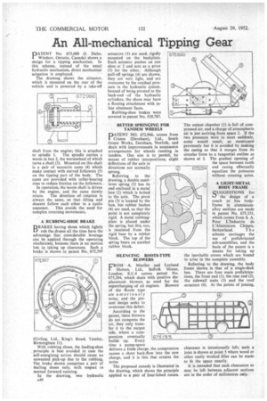
PATENT No. 675,600 (J. Dube. Windsor, Ontario, Canada) shows a design for a tipping mechanism. In this scheme, instead of the usual hydraulic mechanism, direct mechanical actgation is employed.
The drawing shows the abtuator.. which is mounted on the rear of the vehicle and is powered by a take-off shaft from the engine;this is attached to spindle 1. The spindle carries a worm in box 2, the wormwheel of which turns a shaft (3), Mounted on this shaft is a pair of eccentric cams (4) which make contact with curved followers (5) on the tipping part of the body. The cams are provided with roller-bearing rims to reduce friction on the followers..
In operation, the worm shaft is driven by the engine, and the cams slowly rotate. The direction of rotation is always the same, so that lifting and descent follow each other in a cyclic sequence. This avoids the need for complex reversing movements.
BRAKES having shoes which lightly rub the drums all the time have the advantage that considerable leverage can be applied through the operating mechanism, because there is no motion lost in taking up clearances. Such a brake is shown irk patent No.. 675,597
(Girling, Ltd., King's Road, Tyseley, Birmingham 11).
With rubbing shoes, the leading-shoe principle is best avoided in case the self-energizing action should cause an unwanted pick-up due to the rubbing. The brake shown comprises a pair of trailing shoes only, with respect to normal forward running.
In the drawing, two hydraulic A40
actuators (1) are used, rigidly mounted on the backPIate. Each actuatot pushes on one shoe at 2 and acts as a pivot
(3) for the other. Although pull-off springs (4) are shown, they are very light, and are overcome by the residual pressure in the hydraulic system. Instead of being pivoted to the back-end .of the hydraulic cylinders, the shoes may have a floating attachment with inline abutment faces.
Rubbing-shoe brakes were covered in patent No. 519,787.
BETTER SPRINGING FOR TANDEM WHEELS
PATENT NO, 672,966, comes from Cranes .(Dereham), Ltd., South Green Works, Dereham, Norfolk, and deals with improvements in suspension arrangements for wheels running in tandem. One aim is to permit, by means of rubber interpositions, slight deflections of the axle in directions not normally sprung.
Referring to the drawing, a double cantilever spring (1) has its end enclosed in a metal box (2) which is bolted to the axle. The pivot pin (3) is located by the box, but rubber bushes (4) are used, so that the point is not completely rigid. A metal rubbingplate is placed under the spring, but this, too, is insulated from the rigid base by a rubber block. The top of the spring bears on another rubber block.
SILENCING ROOTS-TYPE BLOWERS
FROM A. Mueller and Leyland IMotors, Ltd., Suffolk House, London, E.C.4 comes patent No. 675,204, which deals with positive displacement blowers as used for the supercharging of oil engines. Blowers of the Roots type are notoriously noisy, and the present design seeks to overcome this defect.
According to the patent, these blowers do not compress the air, they only transfer it to the output side, where a compression eventually builds up. Every time a pump-space delivers a fresh charge, the compression causes a short back-flow into the new charge, and it is this that creates the noise.
The proposed remedy is illustrated in the drawing, which shows the principle applied to a pair of four-lobed rotors.
The output chamber (1) is full of compressed air, and a charge of atmospheric air is just arriving from space 2. If the two pressures were to meet suddenly, noise would result, as mentioned previously but it is avoided by making the casing so that it merges from its circular form to a tangential outline as shown at 3. The gradual opening of the space between tooth and easing effectually equalizes the pressures without creating noise.
A LIGHT-METAL BODY FRAME QUGGESTIONS for ts-./ the design of a coach or bus bodyframe in aluminiumalloy sections are made in patent No, 675,133, which comes from S. A. Pour L'Industrie de L'Alumin i um Chippis,
Switzerland. T h e scheme envisages the use of prefabricated sub-assemblies, and the basis of the patent is a means for taking up the inevitable errors which are bound to arise in the complete assembly.
Referring to the drawing, the body frame shown is that of a single-deck bus. There are four main prefabrications, the front end (1), the rear end (2), the sidewall units (3) and the roof structure (4). At the points of joining,
clearance is intentionally left.; such a joint is shown at point 5 where wood or other easily worked filler can be made to fit the space exactly.
It is intended that such clearances as may be left between adjacent sections are in the order of millimetres only.