


,A Resume of Recently Published Patent Specifications
Page 50
If you've noticed an error in this article please click here to report it so we can fix it.
An Opposed-piston Engine
THE usual type of engine disposes of its waste gases long before all the energy has been removed from them, and patent No. 588,194, by W. Wilson and R. Sutcliffe, " Eridge," Leith Park Road, Gravesend, seeks to avoid this waste.
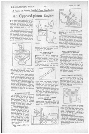
The drawing shows a section of the proposed engine which employs opposed pistons working in a co-axial cylinder. The pistons are not the same size, the one shown on the right being the larger. Each piston is connected by linkages to its own crankpin, but the latter are not spaced equi-angularly. The setting is such that when the larger piston is at full instroke, the smaller piston is 67i degrees ahead of its own upper, dead centre.
In action, the small piston receives an early power thrust, whilst the larger piston takes up the work as the turning effort of the small one dies away, the effect being rather like compounding on a steam engine. It should be noted that the valve and ignition are timed to the motion of the large piston. The proportions between the two pistons are intended to be such that the volume of expansion is equal to the induction vol u me.
A MOBILE CONVEYER
AMOBILE conveyer for facilitating the loading of lorries is shown in patent No. 588,148 by the Wolseley Sheep Shearing Machine Co., Ltd., and H. Macnamara, both of Electric Avenue, Wilton, Birmingham. Intended chiefly for farm work, it can also be used for general lifting purposes.
The drawing shows the outline of the machine, which, although not self-propelling, carries an engine (1) and a gearbox (2) for driving the elevating conveyer (3). The last consists of a chain fitted with Slats, its height being varied by a handoperated block and tackle (4). In use, it projects over the lorry, to which it is coupled by a bar (5).
When being towed for long distances, the rear end is attached to the tractor vehicle and the weight carried by 'the large pair of wheels.
BUS HEATING AND VENTILATION
PATENT No, 588,457, showing an improved means for heating and ventilating passenger vehicles, comes from Clayton Dewandre Co., Ltd., and H. Blomely, both of Titanic Works, Lincoln.
The drawing shows a fragmentary view of a double-deck bus with The system fitted. The impeller (1), located high up on the cab, delivers air into a transverse duct (2), where it is divided between the upper and lower decks, emerging through outlets (3 and 4).
A further scheme shows ducts running along the full length of the body on both floors, with equally spaced distribution grilles. The heater may be of the water-heated type,, covered by an earlier patent (371,878).
POWER-DRIVEN MANURE SPREADER
ONE of the most tedious of farming operations is manure spreading, and patent No. 587,974 shows how this
operation can be mechanized. The patentee is R. Smith, 21, Southdene, Filey, Yorks.
The machine comprises a povs er-lifted unit (1) and a rotary slicer and spreader (2). In operation, the machine is backed into a heap of manure and a load is impaled on the tines (3). It then travels ever the field, during which time the load is slowly lifted into the orbit of the rotary spreader. The machine may also be used as a plain transporter by putting the spreader out of action.
FINE ADJUSTMENT FOR TORSION-BAR SPRINGS
HOW to provide a fine angular setting for torsion bars, without employing high-precision splines, is shown in patent No. 588,235, by W. Berry and Jonas Woodhead and Sons, Ltd., both of Kirkstall Road, Leeds.
The bar is formed as shown in the drawing, each end being shaped to a regular polygon. One end has one more flats than the other, so that by removing the bar from its anchorages and turning it through one flat, a vernier effect is produced.
A SLEEVE-VALVE MECHANISM
ASLEEVE valve, claimed to require short travel and to be free from heat distortion, forms the ,subject of patent No. 588,569, from G. Bunn, 136, Middleton Hall Road, Birmingham, 30. The valve described is of rotary-cumreciprocating pattern.
Referring to the drawing, the cylinder wall is provided with two sets of ports (1 and 2) for inlet and exhaust respectively. The ports, seven in a set, are spaced circumferentially inside two chambers (3 and 4). The sleeve is multi-ported, and describes a motion indicated by the ring (5).
• By having a large number of ports, a large area can be obtained, without recourse to a long stroke. The patent covers changing direction of rotation of the engine by reversing the direction of the sleeve valve.