


Crossley Trolleybus Chassis for 72-passenger Load
Page 29
If you've noticed an error in this article please click here to report it so we can fix it.
NEW progress in trolleybus design is exemplified in an interesting chassis
. now being produced by Crossley Motors, Ltd., Errwood Park, Stockport. This design is of the two-axle type and accommodates a single-deck body sshich has a capacity for 40 seated and 32 standing passengers.
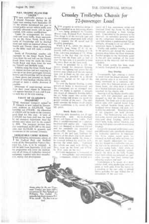
Width is 8 ft„ whilst the chassis is Unusually long, being 32 ft. lo ins. Overall, with a front overhang of 7 ft. 5 ins, and .a rear overhang of 7 ft, 10 ins. Owing to the fact that the frame is curved over the front axle as well as over the rear axle, it is possible to keep the entire floor on the same level.
Power is provided by a 125 h.p. motor, wound for rheostatie braking. Current for lighting and power for the control gear, which is of the low-tension type and is fitted on the near side of the chassis, is provided by a 24-volt generator, carried on the end of the motor shaft.
To meet the heavier braking, a cornpressed-air brake is incorporated, and the connections are so arranged that, when the brake is applied, it actuates two stages of rheostatic braking before the air brake comes into action; thus brake facings and drums are saved the greater portion of the wear. The right pedal operates the brakes on all wheels, whilst acceleration is by means of the left pedal.
Sturdy Brake Units Braking units themselves are of rigid construction, with 16-in.-diameter drums and liners of 4-in. width. Each shoe is straddle-mounted on a separate
hardened-steel anchor pin. pe ra i in g cams are designed to minimize friction and the camshafts are mounted on needle-roller bearings. Shoe return springs of the leaf type facilitate the removal of the shoes, and easily detachable brake drums enable the shoes to be removed without the need for with
drawing the wheel hubs. Ventilated disc wheels are used, with 10.5-in. by 20-in. tyres on the front and 9.75-in. by 20-in. tyres on the rear.
• Air-brake equipment is composed of a two-cylinder unit-construction compressor, which is bolted to a motor of I h.p. continuous rating and insulated from the frame by dry-spot insulation providing a longleakage path. Controlled by the pressure in the reservoir, an automatic governor starts up the compressor whenever the pressure falls below a predetermined figure; similarly, charging is cut out when a set maximum figure is reached.
Visible and audible warning is given in the driver's cab should the reservoir pressure drop below the fixed minimum. Further gauges on the instrument panel in the cab give readings of the exact pressure in the reservoir and the brake cylinders.
The whole system has been made as nearly fool-proof as is possible.
Easy Steering
Exceptionally light steering is stated to result from the design adopted. The side steering tube is in two parts, both being connected to a common relay lever, with rheafulcrum points at different levels; the relay lever is carried on a hushed fulcrum point in a bracket mounted on the chassis side.
Steering is of the Marles double-roller type, with full adjustment and joints designed so that the links cannot get displaced. The front axle is the reversed Elliott type, with tapered swivel kingpins, vertical loading being taken by hardened thrust buttons and pads situated on the underside. Wearing surfaces of the king-pins are hard chromeplated. The load-carrying axle beam, stub axles, swivels and steering arms are alloy-steel drop forgings, whilst the wheel hubs, brake anchor brackets, and. steering ball joints are carbon-steel drop forgin gs.
A centrally disposed underslung worm and differential unit, specifically designed for trolleybus operation is employed. 'Ube n. centre worm gears are mounted on ball and roller hearings and do not require adjustment for wear; they are housed in a malleable iron casing and can be removed as a unit from the axle casing body. Axle shafts of 80-85-tort steel, with multiple splines, convey the drive to the fully floating wheel hubs which are mounted on taper roller bearings that have vernier-type adjusting washers and nuts.
Transmission is by means of a short tubular shaft, with needle-type universal joints at both ends, from the motor to a coupling at the rear axle; a spline() sleeve provides for any sliding due to movements of the rear axle.