


PATENTS SUMMARIZED.
Page 22
If you've noticed an error in this article please click here to report it so we can fix it.
A Novel Agrimotor.
An agrirmotor of a novel and ingenious construction forms the subject of a patent by G. W. and A. A. Woodhouse (No. 117,125). The chassis is a threewheeled one, the drive being transmitted through the front single wheel, two small castor wheels at the rear end of the chassis being incorporated in this unusual design.
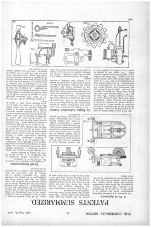
The front wheel might almi>st be said to be supported by gymbals. Bolted to the front end of the chassis is a circular structure of channel steel. In this bears a drum, round one portion of which is wound the steering chain. Supported from the drum, and inside it, is an inverted U-sha.lied frame_ The legs of the " II " project downwards below the evel of the drum, and serve as supports for the axle. Also carried by these legs, and positioned high enough above the drum to be clear of the roadwheel, is a countershaft. In the centre of the base or horizontal bar of the." " is a vertical shalt which has crown bevel wheels top and bottom. The lower one meshes with a small bevel pinion on the countershaft. The upper one is geared to another bevel wheel on a shaft which is driven by the engine through chain sprockets and roller chains. The front axle is also chain driven from the countershaft above mentioned.
It is clear from the construction that the U-shaped framing, the circular drum, the front axle, and the front driven wheel can all be turned together by pulling in one direction_ or the other on the steering chains, and such movement has no effect on the drive gear as
An Engine Lubrication System.
C. G. Pullin has devised a very coinplete and interesting system of engine lubrication, and he describes this in his specification No. 117,100. The power to drive the oil pump is derived from the fluctuations of pressure within the engine crankcase. The pressure acts upon the enlarged, piston-like end of the pump plunger, the arrangement being that excess of pressure within the crankcase pushes the plunger outwards on the delivery stroke, and it is returned by means of a spring, thus effecting a suction stroke.
Delivery from the pump is taken via a pipe to the main bearings. Inside the bearing a groove is cut of such a length as may be necessary to allow of a auffi
ciency of oil being carried through a hole in the crankshaft to the crankpin, whilst oil is also lubricating the main • bearing during such time as the groove and hole in the crankshaft are not in communication. A similar arrangement within the big end bearing allows of oil being carried to the gudgeon pin, and, again, by the same means, from the gudgeon pin to the piston and cylinder walls. The important feature is the timing of the lubrication by predetermining the lengths of the grooves in the bearings.
Detail Improvements.
A useful pipe wrench is the subject pf No. 117,139, by W. J. Hampson.
An American patent described in. No. 117,129 by J. L. Garver has to do with the design of flexible wheels.
A simple safety coupling for motor tractors allowing of automatic detach• ment when the implement in use meets with an unexpected resistance forms the subject of No. 117,150, by A. Nicholson. No. 117,167, by A. A. Hello, concerns a multi-jet carburetter. The jets are disposed horizontally round a vertical choke tube, the area of the choke being determined by the position of a conical plug which is moved up and down by means of the throttle valve control lever.
W. G. Bugg, in No. 117,182, illustrates a design of engine valve. The ordinary spring washer and its cotter are replaced by a ball thrust race and cotter. A shoulder is formed on the valve stem, and against this shoulder beds a sleeve which on its exterior surface carries a thread. The thread bears in a correspending portion of the valve guide. The object is to cause the valve to revolve slightly every time it opens or shuts.
A useful invention of No. 117,131, by W. T. Reid. The patentees principal concern appears to be the aeroplane engine, and he has designed a rotary piston pump, contained within the hub of a fan or propeller. As designed, the idea is apparently that this propeller and pump shall be so disposed on the fuselage of the aeroplane or chassis of a moving vehicle that as they move through the air the propeller is caused to revolve and so works the pump, which provides pressure for the fuel tank of the chassis or aeroplane, when the fuel supply system is not gravity fed.