


Patents Completed.
Page 22
If you've noticed an error in this article please click here to report it so we can fix it.
An Automatic Adjusting Splash Guard, F. G. Gill, No. 26,390, dated 25th November, 1911.—This specification describes a method of suspending side splashguards or fenders for wheels of motor vehicles. A link is suspended from the wheel hub, and the guard is pivoted on the link so that it always hangs horizontally however the suspend ing link may oscillate; it is also enabled to swing without greatly varying the horizontal position of its lower edge. The suspending link may be made adjustable as is shown in the drawing, or the guard may be mounted on a second link pivoted to the first, and be vertically adjustable on that link.
A Sell-cleaning Plug.
C. E. Johnson, No. 11,311, dated 13th May, 1912—This plug is rendered selfcleaning by the provision of a valve through which the exhaust gases can be allowed to escape. This action very quickly cleans off any deposits which may have been made. The central porcelain rod is secured in the ordinary way in a bushing which is screwed into the body of the plug. The porcelain rod is smaller than the interior of the body of the plug, and a passage is provided up to the bushing. This passage is furnished with a seating, which can be screwed down to close the passage, or, alternatively, it can be screwed up to put it in communication with lateral ports to the atmosphere_ When the engine is running, by unscrewing the bush• ing, the cylinder contents under high pressure are allowed to escape through the plug, which is thereby thoroughly cleaned.
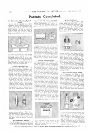
A Change-over Switch.
A. H. Midgley and C. A. Vandervell, No. 21,441, dated 28th September, 1911. ---This invention relates to an improved
form of coil and switch mechanism, which can be easily manufactured and fitted to the dashboard of a vehicle. A circular fibre tube has fitted inside it an ignition coil unit. This unit consists of
a high-tension coil with primary and secondary windings, and a condenser. At one end of the tube is fitted an insulating plate carrying the switch contacts; in front of this is a disc on which are mounted suitable contacts for making connection as required with the contacts on the terminal plate. This switch disc is held in place by a metal flange screwed on to the front of the cylinder.
Electric Transmission.
H. kleinschmidt, No. 18,051, dated 9th August, 1911.—This specification describes a dynamo-electric transmission gear suitable for use on motor vehicles, the essential feature of which is the use of uni-polar machines. In the construction illustrated, two such machines are built back to back with a single stator and two rotors arranged closely side by side. One of these acts as a generator and the other as a motor. Two field windings are provided, one for each machine, and these may be located either on the stator or the rotor. Copper rings are fixed round the two rotors beside the coils, and on the stator between the two rotors, to increase the electrical conductivity and to prevent magnetic leakage. The stator casing is filled with mercury or some other body. This is provided in order to convey current from the rotors to the stator, so that circulation of current is possible as is indicated in the drawings. In operation, the generator rotor is driven direct from the engine, and when its field is excited a current is induced, circulating in the two rotors and the stator. If now the motor field be excited, the interaction with this current causes the motor to revolve at a speed depending on the strength of the field, so that any speed range is obtainable; the motor, also, is reversed by reversing the field.
A New Nut Lock.
D. P. Jones, and Bicones Ltd., No. 12,084, dated 21st May, 1912.—According to this invention the main nut is provided with a conical recess into which the tapered sleeve of a locking member enters. This locking member has a flange which bears against the part being tightened up when the nut is screwed in place. The flange is split at one or more places, and lugs are produced by bending up the split ends as shown clearly in the small figure. The sleeve and the flange are also split completely through at one side to allow the sleeve to be compressed on to the bolt. by the tapered walls of the recess in the, nut. In operation, the turned-up lugs on the locking member exert a locking action on the main nut in advance of the locking action which is exerted by the compression of the split sleeve of the locking member.
A Clever Semi-rotary Valve.
D. J. Sweetzer, No. 25,291 of 1911, Cognate Application No. 26,335 of 1911, dated 14th November, 1911.—The valve casing in this invention consists of a closed cylindrical chamber arranged transversely on the top of the cylinder, arid preferably cast integrally with the cylinder and jackets. The valve itself is a cylinder with longitudinal pockets cut on opposite sides of it. The inlet and exhaust ports are arranged on each. side of the valve casing, and are placed, in communication with the cylinder port. by the pockets in the valve as it oscillates one way or the other. The required motion is given to the valve by a. cam mounted on the half-speed shaft and provided with a suitably-shaped groove. On the end of the valve spindle. is fixed an arm engaging this groove so that the valve is oscillated to give therequired valve motion.