


Scammell Gearbox
Page 70
If you've noticed an error in this article please click here to report it so we can fix it.
A POWER-OPERATED gearbox is in. described in patent No. 831,486. It has four speeds and reverse, with another two-speed box in series, giving eight forward speeds and two in reverse. (Scammell Lorries, Ltd., Tolpits Lane, Watford West.)
The two gearboxes are epicyclic and the ratios are selected by braking the various drums. The braking force is provided by pneumatic cylinders, one to each drain, and the subject of the patent is the manner in which the driver controls the gearboxes.
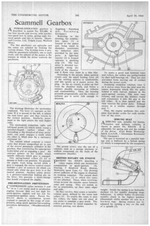
The drawing illustrates the mechanism employed. The lever (1) operates as follows: If it is moved to the left, it selects the next lower gear and then returns to the vertical position. Similarly, movement to the right selects the next higher ratio.
The mechanism comprises rightand left-hand pawls (2) which notch round a sprocket-shaped ratchet wheel (3). According to the direction of lever movement, one pawl engages a tooth while the other is lifted clear by a stationary abutment (4).
The ratchet wheel controls a rotary valve that directs comprei-sed air to one of the several pneumatic cylinders in the gearbox, thus constricting the appropriate brake-band 'and so engaging a gear. An external pointer on the ratchet wheel spindle indicates which gear is engaged.
Two spring-loaded rollers (5) act as detents to hold a set position. To prevent the engine from being started while a gear is engaged, the starter control circuit includes a pair of contacts (6) which are closed only when the gear lever is in the neutral position. Another safety device is a governor-controlled locking pin on the lever; this prevents a down-change that would overspeed the engine.
PRE-DETONATION PREVENTION COMPRESSION ratios between 9 and 14 to I are rarely used in production engines because they are too high for spark-ignition engines and too low for compression-ignition units. Patent No. 831,311 shows a combustion system claimed to operate in this range of compression, using spark ignition but avoiding premalure detonation. (Maschinenfabrik c32 Augsburg Nurnberg A.G., Nurnberg, Germany.) Referring to the drawing, the combustion space (1) is located in the piston and, being small in diameter, accelerates the induction swirl provided by the inlet ports. A light-fuel injector (2) is located opposite a sparking plug (3). The fuel spray is directed tangentially along the walls of the chamber and it flows over them in a thin film.
According to the patent, when ignition occurs only the small leading front (4) of the swirling mixture is combustible. and this ignites as it passes across the plug. As the air rotates, it picks up fuel from the chamber walls, and forms a mixture steadily increasing in richness and combustibility. Thus, the burning proceeds progressively, and the residue of unburnt gas is never rich enough to detonate.
The patent covers also the use of a catalyst, such as a spongy platinum or sodium compound, on the walls of the combustion chamber.
BRITISH ROTARY 011, ENGINE
PATENT No. 829,872 describe a a rotary engine which can incorporate
compressionor spark-ignition. (A. Fearing, 5 Stratford Road, Heaton, Newcastle upon Tyne, 6.) The drawing shows sufficient of the engine to illustrate its working sequence. The output shaft carries a rotor (1) to which two vanes (2) are attached. These, when revolving, sweep around the annular space between rotor and casing. They are sealed, as far as practicable, on their outer edges and ends.
As they revolve, they create a variablevolume space, defined by the vanes and rollers (3). To enable the vanes to pass the rollers, the latter are cut away at one point to simulate a gear tooth. The rollers are driven in timed sequence by external gearing, not shown. To make a good seal between rotor and rollers, the rollers are spring-loaded by their half-bearings (4). They are also prevented from moving out of contact during the power cycle.
Assuming clockwise rotation, vane 5, as it moves away from the inlet port (6), causes depression which fills the space behind it with fuel-air mixture in the spark-ignited version. The next vane follows, and carries the mixture round and compresses it into the gap in the left roller. It is then ignited and the vane receives the power pulse. Exhaust occurs in a similar manner through port 7.
Thus, the engine performs two complete four-stroke cycles for each revolution of the rotor.
SPRUNG SEAT
A SPRUNG seat, suitable for lorries, rt tractors and military vehicles, is shown in patent No. 830,934. It is adjustable for spring rate and the weight of the driver. (Carl Bruns Werkzeugfabrik G.m.b.H., 1 Eikestrasse Kreiensen/ Harz, Germany.)
The seat is mounted on a parallel linkage and is buffered by a helical spring (1) which is compressed by the occupant's weight. Inside the spring is an hydraulic dashpot (2) for rapidly damping large deflections A rubber buffer (3) prevents metallic shock in the highest position (illustrated) whilst another (4) acts as a low-level stop. Spring tension can be adjusted by turning a key on the end of a spindle (5).