


NOVEL SUSPENSION for
Page 46
Page 47
Page 48
If you've noticed an error in this article please click here to report it so we can fix it.
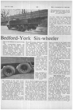
Bedford-York Six-wheeler
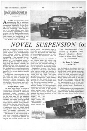
York Trailing-wheel Conversion of Bedford 7-ton Chassis Employs Rocker Arms to Give High Degree of Articulation By John F. Moon,
ANOVEL linkage system, which eliminates the use of additional non-staddard springs and gives independent svspension for the trailing wheels, characterizes the York third-axle conversion. This design is one of two quite different types which have been fully approved by Vauxhall Motors, Ltd., for application to certain Bedford normaland forward-control 7-ton chassis, as announced in The Commercial Motor on March 25.
The Bedford-York six-wheeler pro
vides an inexpensive vehicle for the haulier Who wishes to carry a clear 10-ton payload on a mass-production 7-ton chassis without drastically shortening the chassis life by severe overloading. Fully equipped, the sixwheeled chassis-cab based on the Bedford SL 13-ft.-wheelbase model is listed at £1,803 15s. This is £660 15s. more than the standard 7-tonner, the additional price being accounted for by £555 for the York conversion, £95 for the Bedford two-speed axle (which is obligatory because of its load rating) and £10 15s, for the Bedford chassis flitch plates.
A prototype York conversion of an SL model has been road tested and was found to have an average performance, giving reasonable fuel economy, adequate acceleration and hill-climbing performance, and sufficient braking power to ensure safety.
Unique Bogie Layout The York bogie layout is unique in this country. The trailing wheels are carried at the rear ends of substantial fabricated rocker members, the forward ends of which are connected to the rear ends of the standard Bedford main springs by swinging shackles. The rocker arms are pivoted an trunnion brackets, which are bolted to the chassis frame immediately behind the rear ends of the main springs. Thus the total bogie loading is transferred from the chassis frame through four points only, whereas in most six-wheeler conversions six suspension-location points are used.
The position of the rocker pivots is such that a constant .weight-distribution ratio is maintained between the driving and trailing wheels, but this ca can be altered. The forward ends of the rocker, arms have two sets of drillings, and, by moving the lower ends of the shackles from one set of holes to another, the distribution ratio can be varied.
When the shackles are connected to the forward holes the driving axle carries 55 per cent, of the bogie load, whilst with the shackles attached to the rearmost holes, 60 per cent. of the load is imposed on the driving wheels.
Connection between the shackles and the rear ends of the main springs' is by brackets, which are attached to the standard rear shackle pins and are folded over the upper four mainspring leaves. Thus, the rear ends of the main spring leaves "float 7 and are attached to the chassis frame only through the shackles, the rocker arms. and the rocker-trunnion brackets.
Inverted U extensions of the shackles forward of the main-spring attachment points are intended to bear against the rear ends of the standard helper springs under full load. In practice this condition never occurs, because the relative positions of the shackles, the main springs and the helper springs always remain virtually constant.
Helper-spring reaction brackets can not be fitted to the chassis frame to bring the helper springs into play. To do so would reduce spring movement, which, in turn, would cut down the degree of bogie articulation—one of the features of the York layout. The helper springs carry little of the load, so that the standard main .springs, which are designed for a load of 5,500 lb., are subjected to 60 or 55 per cent. of the total bogie loading. It is understood, however, that a modification is in hand.
Standard Bedford driving-axle tubes are welded to the York trailing armi, and carry hubs, bearings, brake assemblies and brake drums similar to those used on the Bedford two-speed driving • axle.
The trailing-wheel brakes are actuated by the rear half of the Bedford-Lockheed tandem master cylinder, whilst the driving-axle brakes have a separate vacuum hydraulic circuit consisting of a Clayton Dewandre 91-in.-diameter Hydrovac and hydraulic master cylinder, the actuation of which is controlled by the line pressure in the main circuit.
The hand-brake linkage is simple and consists of a compensating relay linkage attached to the chassis crossmember ahead of the driving axle. From the rear of this linkage a cable leads to the driving-axle compensator linkage and another cable goes to a compensating linkage on the trunn ionbracket cross-tube, which in turn actuates separate cables to each trailing-wheel brake bisector.
Essentially simple also is the modification carried out to the standard Bedford chassis frame. In the case of
SS and SL models, which are available with Bedford-fitted flitch plates, channel-section extension members, +-in. thick with a maximum depth of 10+ in. and 3-in.-wide 'flanges, are butt-welded to the flitch plates and riveted to the Bedford side members. In the case of SE and J65 and J6L chassis, no flitch plates are offered, so York make their own and weld the channels to them.
There is a choice of three power units: Bedford 300-cu.-in. petrol and oil engines and the Leyland 0.350 oil engine. These have gross power outputs of 133 b.h.p., 94 b.h.p. and 105 b.h.p. respectively. When the two Bedford engines are fitted, the maximum permissible vehicle weight is 15 tons, which is raised by 8 cwt. when the Leyland engine is installed.
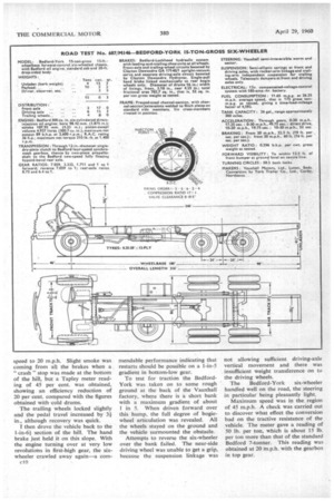
The test vehicle had the Bedford oil engine, and, complete with 20-ft. dropsided timber body, its kerb weight was 4 tons l31 cwt. The driving-axle loading was 1 ton 101 cwt., whilst the trailing-wheel loading was 1 ton 3 cwt.
Laden with concrete test weights, the gross weight of the vehicle, complete with Vauxhall's Colin Prebble and myself in the cab, was 15 tons 01 cwt. The driving axle was carrying 6 tons 151 cwt., whilst the trailing-wheel loading was 4 tons 8 cwt. Thus the driving wheels were carrying 60 per cent, of the load, although in theory they should have been taking only 55 per cent., bepuse of the shackle position.
Braking tests showed that, when making full-pressure stops from 30 m.p.h., the trailing wheels locked, but no wheel locking occurred when conducting similar stops from 20 m.p.h. The stopping distances measured were reasonably satisfactory and retardation figures recorded by the Tapley meter indicated a maximum efficiency of 65 per cent. Application of the hand brake from 20 m.p.h. gave average meter readings of 30 per cent.
Acceleration figures obtained both from a standstill up to 30 m.p.h., and in top gear, low axle ratio, between 10 m.p.h. and 30 m.p.h., were satisfactory, and the smoothness of the transmission during top-gear tests from as low as 5 m.p.h. was noteworthy, although slight rattle occurred at about 11 m.p.h.
The six-mile undulating consumption route between Barton and Clophill normally used for Bedford tests was employed for the six-wheeler. Two runs were made, one with Colin Prebble driving and the other with myself at the wheel. Both tests produced identical results in terms of average speed and fuel-consumption ratio. The final figures were 11.65 m.p.g. at 26.25 m.p.h. average speed.
Hill-climbing Tests
For the hill-performance tests the vehicle was taken to Bison Hill, which is 1 mile long and has an average gradient of 1 in 101. The ascent was made in an ambient temperature of 44° F. and lasted for 5 minutes 50 seconds. The coolant temperature at the top of the hill was 163° F., which is less than 10° F. above its normal value. The lowest ratio combination employed, first-high, was in use for 2 minutes 10 seconds, during which time the minimum road speed observed was 4 m.p.h.
A fade test lasting 2 minutes 20 seconds was made by coasting the Bedford-York down the hill in neutral, using the foot brake to restrict the
speed to 20 m.p.h. Slight smoke was coming from all the brakes when a " crash " stop was made at the bottom of the hill, but a Tapley meter reading of 45 per cent. was obtained, showing an efficiency reduction of 20 per cent. compared with the figures obtained with cold drums.
The trailing wheels locked slightly and the pedal travel increased by 3,1 in., although recovery was quick.
I then drove the vehicle back to the section of the hill. The hand brake just held it on this slope. With the engine turning over at very low revolutions in first-high gear, the sixwheeler crawled away again—a cornc) mendable performance indicating that restarts should be possible on a 1-in-5 gradient in bottom-low gear.
To test for traction the BedfordYork was taken on to some rough ground at the back of the Vauxhall factory, where there is a short bank with a maximum gradient of about 1 in 5. When driven forward over this hump, the full degree of bogiewheel articulation was revealed. All the wheels stayed on the ground and the vehicle surmounted the obstacle.
Attempts to reverse the six-wheeler over the bank failed. The near-side driving wheel was unable to get a grip, because the suspension linkage was not allowing sufficient driving-axle vertical movement and there was insufficient weight transference on to the driving wheels.
The Bedford-York six-wheeler handled well on the road, the steering in particular being pleasantly light.
Maximum speed was in the region of 45 m.p.h. A check was carried out to discover what effect the conversion had on the tractive resistance of the vehicle. The meter gave a reading of 50 lb. per ton, which is about 15 lb. per ton more than that of the standard Bedford 7-tonner. This reading was . obtained at 20 in.p.h. with the gearbox in top gear.