


A Three-wheeled Battery electric Van Chassis
Page 54
If you've noticed an error in this article please click here to report it so we can fix it.
A Résumé of Recently Published Patent Specifications PATENT No. 481,661 discloses details of a battery-driven threewheeled vehicle of the parcel-car type, and comes from A. E. Morrison and Sons, Ltd., Brunswick Works, South Wigston, Leicestershire, The design incorporates a single front wheel, which forms a complete driving and steering unit, the motor (4) being connected by chain to a spindle (1), from which a further chain drives the wheel. Suspension is by means of a leaf spring (3), Which is shackled to a bar (2) attached to the wheel axle, the assembly having a scissor-like action about the spindle.
The essence of the patent is the location of the point of pressure of the leaf spring; this is directly above the wheel centre so that, although a onesided fixing is employed for ease of detachment, the wheel does not tend to slope sideways when cornering.
Safety Measures for Hydraulic Brakes, guard against complete failure should any component fail, is the object of an hydraulic-cum-mechanical braking system, described in patent No. 481,608, by Automotive Products Co., Ltd., Brock House, Langham Place, London, W.1, F. G. Parnell and A. F. Martindale. Dealing with the hydraulic system first, the pedal operates a transmission-driven frictional booster (2), which directs an increased force on to a master cylinder (3). A dual piston at this point con trols two separate hydraulic systems, that of the pipe (5), which operates on only the front wheels, whilst the other (pipe 4) serves all wheels. Note the two-diameter cylinders ,(1) of the front wheels; these are hydraulically separate, although formed in a unit.
The mechanical .system, operating the rear brakes, is worked also from the booster (2); the drawing clearly shows the rod-work for these, also the cam-and-lever movement for spreading the shoes.
a44 Novelty in Hydraulic-transmission Systems.
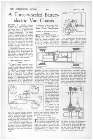
HYDRAULIC-TRANSMISSION sysItems have always possessed a fascination for the inventor, and patent No. 481,093 discloses a novel scheme of this nature. The patentees are E. W. Aspden and W.A.S.P. Engineering Co., Ltd., Cocker Street, Blackpool. In brief, the system comprises an engine-driven master pump. in conjunction with a fluid motor housed in each road wheel. The drawing shows the outline of the vehicle; the master pump (3) draws oil (or other liquid) from a reservoir (1) and forces it, via a control-valve box (2), to the wheel motors, whence it returns, via a second pipe line. The control valve provides for a reverse, by altering the oil flow, and for braking by an adjustable restriction. The wheel motors are of the positive-drive type, consisting of six radial cylinders operating a single crankpin formed on the wheel spindle.
A feature of the scheme is the use of a variable throw crank on the main oil motor ; this system gives a true infinitely variable gear, although the mechanical efficiency is apt to be on the low side.
Using Tappets for Oil Pumps.
THE problem of lubricating valve gear is solved in an ingenious man. ner in patent No. 481,811, which describes a scheme in which the tappet mechanism is slightly modified to form a cylinder-and-piston oil pump. The patentee is F. J. Tippen, 3, Eastleigh Avenue, Earlsdon, Coventry.
The accompanying drawing shows the system applied to the rocker mechanism of overhead valves, although it is not limited to such an application, and may be modified to suit side valves. The tappet, when at its lowest point, uncovers ports (2) leading to an annular space between tappet and guide. Oil flung from the crankshaft drains down these ports, and reaches the lowest point of the bores in the tappet. Upon the upstroke, the resulting compression forces the trapped oil past a one-way valve (3) whence it passes, via a system of oilways, to the rocker bearing (1).
The inventor states that use may also be made of the principle for cooling the valves ; in this case, hollow valve stems would be used, and a return circuit provided for the oil.